Published · CERAMIC CNC Engineering · Engineering Guide · 13 min read
Machined Ceramic Components for Optical and Laser Equipment
Select and specify ceramic mounts, spacers, alignment fixtures, apertures, insulating supports, and thermal interfaces for optical and laser equipment RFQs.
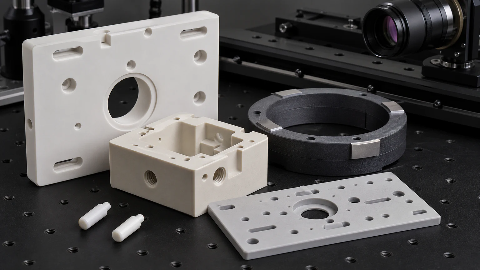
For an optical or laser assembly, specify the ceramic part by the interface it controls: optical-axis location, mount flatness, bore or aperture position, thermal path, electrical isolation, vacuum boundary, or clean contact. Final optical performance cannot be inferred from a ceramic material name or a dimensional report alone.
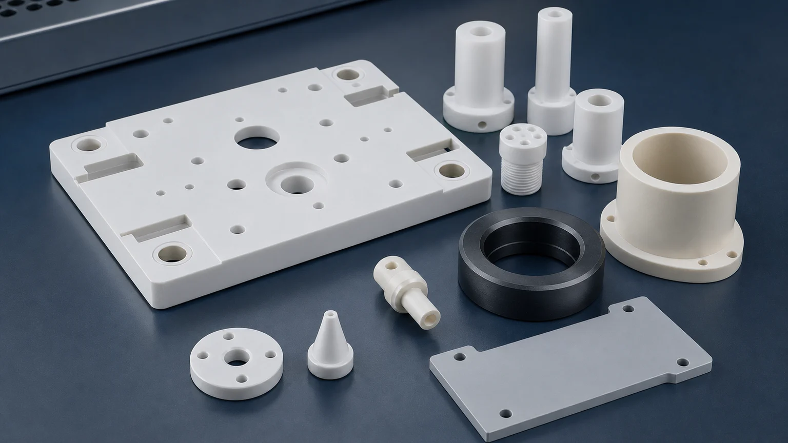
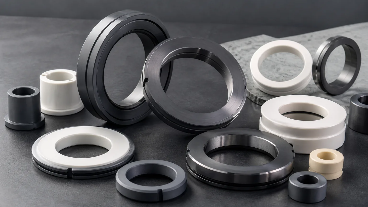
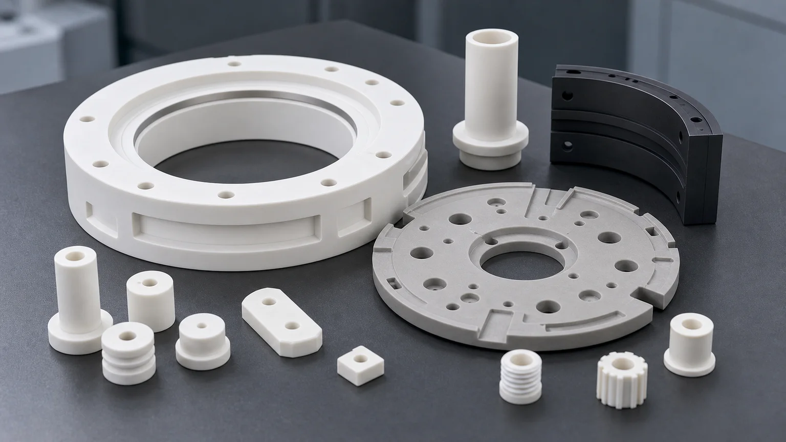
Machined ceramic components can support optical benches, industrial laser heads, fiber-alignment tools, inspection systems, analytical instruments, vacuum optics, and research equipment. Common parts include mounts, spacers, insulating plates, aperture supports, V-groove fixtures, sensor holders, thermal breaks, reference blocks, and structural rings.
The sourcing problem is unusually easy to misunderstand. A drawing may show a plate with several holes, yet one bore defines the optical axis, one face controls focus spacing, and one pad removes heat. Tightening every dimension does not protect those functions. A better RFQ identifies the optical, mechanical, thermal, electrical, and cleanliness interfaces separately and assigns each one an inspectable acceptance method.
This page covers precision ceramic machining and incoming acceptance for structural and support parts. It does not claim optical polishing, mirror figuring, optical coating, lens manufacture, laser-damage qualification, or complete system alignment. Those services and performance tests must be specified and reviewed separately.
Where Machined Ceramics Fit In Optical Systems
Ceramic components are not limited to transparent optical elements. Opaque technical ceramics are often used around the light path because the assembly also needs mechanical location, insulation, heat management, vacuum compatibility, wear resistance, or clean handling.
| Component family | Function in the equipment | RFQ-critical interface |
|---|---|---|
| Lens, mirror, and sensor mounts | Hold an optical or sensing element relative to a mechanical reference | Mounting face, bore axis, shoulder location, clamp contact, assembly stress |
| Laser cavity spacers and insulating supports | Maintain spacing while isolating heat or voltage | Stack height, parallelism, thermal path, creepage or clearance, fastening method |
| Aperture and beam-path supports | Position a hole, slot, mask, or tube around the intended axis | Aperture diameter, position, taper, breakout, edge condition, clean bore |
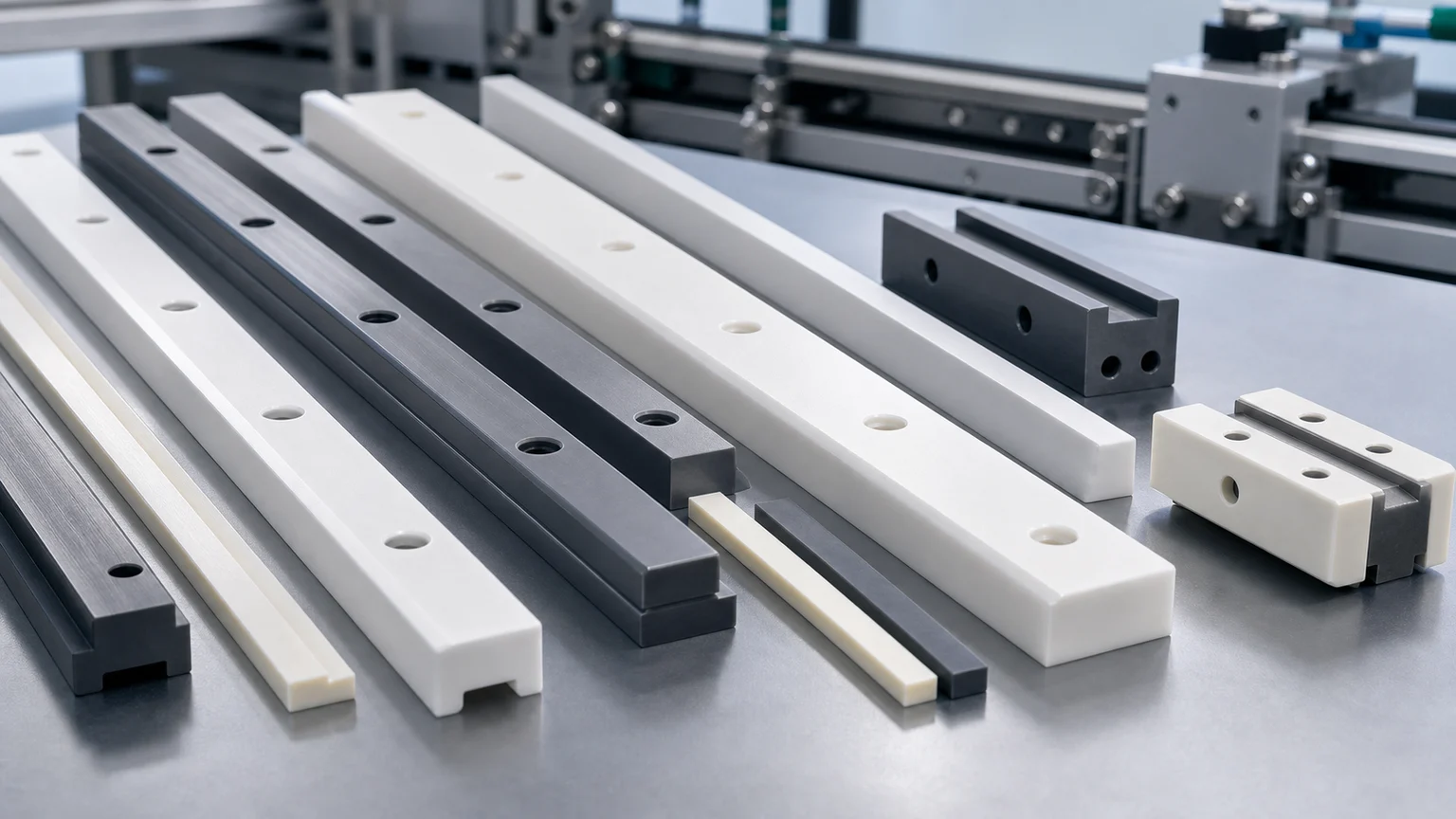
| Fiber-alignment fixtures and V-grooves | Locate fiber, ferrule, or small cylindrical components | Groove geometry, pitch, straightness, contact edge, wear, inspection access |
| Optical-bench fixture plates | Provide repeatable datums for adjustment, test, and assembly | Datum face, hole pattern, slots, locating pins, local pad height, repeatability evidence |
| Vacuum and analytical instrument parts | Support optics or sensors without introducing a conductive or contaminating metal interface | Sealing face, trapped volume, cleaning, bake context, packaging, customer vacuum test |
| Thermal and electrical interface plates | Move or block heat while maintaining electrical isolation | Grade-specific thermal direction, thickness, flatness, Ra, mounting pressure, edge quality |
Kyocera documents ceramic reference jigs and stages for optical measuring instruments, as well as high-precision V-groove fixtures for optical-fiber alignment. These examples support the application logic: the ceramic part is valuable because it preserves a measurable relationship, not because it is simply nonmetallic. Kyocera mechanical and industrial ceramics catalog
Laser equipment is also a durable industrial and scientific application rather than a short-lived search trend. SCHOTT describes laser materials and components across scientific systems and industrial cutting and welding equipment. The machining opportunity here is the surrounding structural, insulating, alignment, and thermal hardware; it should not be confused with SCHOTT’s optical glass products. SCHOTT laser application overview
Draw The Functional Coordinate System First
An optical assembly usually has at least two coordinate systems:
- The mechanical datum system used to manufacture and inspect the ceramic part.
- The optical axis or reference plane used to align the finished instrument.
The RFQ should show how they connect. If a bore is intended to carry a lens barrel, mark whether the bore axis, shoulder face, mounting pads, or an external pilot locates the optics. If the customer aligns the system after assembly, identify the adjustment range and which ceramic features are fixed references rather than adjustable features.
Useful drawing inputs include:
- Optical axis, beam path, sensor centerline, or fiber centerline as a basic reference.
- Mechanical datums used for machining and inspection.
- Lens-barrel, mirror-cell, ferrule, detector, shutter, or aperture interfaces.
- Fixed, adjustable, compliant, bonded, clamped, or threaded mounting method.
- Contact pads, shoulder faces, bores, V-grooves, slots, and alignment-pin locations.
- Thermal source, heat-flow direction, temperature range, and mating materials.
- Voltage, grounding, and isolation boundaries where relevant.
- Vacuum, purge-gas, cleanroom, particle, and packaging requirements.
- Customer-owned optical alignment, wavefront, focus, transmission, or laser test.
Without this relationship, a supplier may inspect the ceramic correctly from the drawing while the part still fails to locate the real optical element.
Material Selection For Optical And Laser Hardware
Do not use a generic “low expansion ceramic” or “laser ceramic” callout. Select an exact material grade from the assembly failure mode and source its property data from the actual manufacturer.
| Material direction | Useful RFQ role | Important boundary |
|---|---|---|
| Macor machinable glass ceramic | Prototype mounts, insulating spacers, cavities, threaded holders, laboratory and vacuum-adjacent geometry | Convenient machining does not make it interchangeable with hard-fired alumina, SiC, Si3N4, or AlN in load, wear, thermal, or production service |
| Alumina | Insulating plates, spacers, sleeves, sensor holders, fixture blocks, clean structural parts | State grade or purity, fired blank, functional faces, edge zones, cleaning, and dielectric qualification owner |
| Silicon carbide | Stiff structural supports, rings, reference bodies, thermally demanding optical structures | Optical-grade SiC, structural SiC grades, joining routes, coatings, and mirror surfaces are not the same supply scope |
| Aluminum nitride | Electrically insulating plates or supports where heat transfer also matters | Use grade-specific thermal and electrical data; protect edges and thermal-contact faces; review moisture and cleaning route |
| Silicon nitride | Slender supports, pins, rollers, or mechanically loaded alignment hardware | Exact grade, loading, thermal cycle, working finish, and blank route need review |
| Zirconia | Compact locating pins, ferrule-adjacent guides, wear contacts, smooth small components | Temperature, aging environment, contact stress, finish, roundness, and mating material matter |
Corning lists MACOR applications in laser systems, laboratory equipment, and vacuum environments and describes it as a machinable glass ceramic supplied as slabs and rods. This makes it a credible material direction for fast-turn complex supports, but the exact design must still stay inside grade-specific limits. Corning MACOR product information
CoorsTek identifies silicon carbide for optical mirrors and structural components where stiffness, mass, and thermal stability matter. That is evidence for SiC’s relevance to optical structures, not evidence that any SiC blank or general ceramic machining route can meet optical-mirror requirements. CoorsTek silicon carbide for optical applications
Use the advanced ceramic material selection guide when the drawing is still material-open. Ask the material supplier for grade-specific thermal expansion, conductivity, elastic, dielectric, temperature, and environmental data under the conditions that matter to the assembly.
Separate Structural Surfaces From Optical Surfaces
The most important scope boundary is the distinction between a ceramic feature that mechanically supports optics and a surface that is itself optically functional.
Structural or mounting surfaces may be accepted by:
- Flatness, parallelism, perpendicularity, or profile from a mechanical datum.
- Bore size, bore axis, shoulder location, or runout.
- Position of holes, slots, pins, pads, or V-grooves.
- Surface roughness on a mounting, sliding, thermal, sealing, or cleanable zone.
- Edge-break and chip criteria around contact and handling areas.
Optically functional surfaces may require separate controls such as figure, waviness, scatter, transmission, reflectivity, coating adhesion, laser-induced damage threshold, or system-level alignment. These are not proven by a standard CMM or Ra report. The RFQ must identify who supplies and qualifies the optical function.
This boundary also prevents misleading requests such as “optical finish” on an opaque mounting plate. Replace that phrase with the actual function: lens-seat flatness, barrel-bore axis, bonded-pad roughness, aperture-edge condition, or clean visible surface.
Machining Route Depends On Material State
MACOR and other machinable ceramics can support conventional milling, drilling, turning, and threading within material-specific design limits. Fired alumina, SiC, Si3N4, zirconia, and AlN commonly require diamond grinding, lapping, or other hard-material finishing for critical dimensions and surfaces.
The route may combine:
- Near-net or green-state forming for economical bulk geometry.
- Sintering with planned shrinkage and stock allowance.
- Diamond grinding of datums, bores, shoulders, and outside profiles.
- Lapping where a named contact face needs improved flatness or finish.
- Micro-drilling, laser processing, or another reviewed method for apertures and small holes.
- Cleaning and protected packaging after final inspection.
Do not prescribe one route before the supplier reviews the blank and geometry. A deep pocket that is straightforward in MACOR may be expensive or impractical to grind into hard-fired SiC. A thin web that survives in CAD may distort during firing or chip during finishing. A custom near-net blank may be appropriate for production but uneconomical for one prototype.
DFM Rules For Mounts, Spacers, And Apertures
Optical hardware often copies familiar metal geometry. Ceramic versions need more deliberate stress and tool-access control.
- Add realistic internal radii to pockets and slot ends.
- Avoid knife edges around apertures unless the optical function requires them and the edge can be inspected.
- Keep threaded holes and precision bores away from thin outside walls.
- Avoid rigid press fits around lens barrels, metal pins, or bushings without stress and thermal review.
- Use compliant clamps, adhesive joints, metal inserts, or separate retainers when they reduce ceramic tensile stress.
- Provide grinding access to datum pads, shoulders, and critical bores.
- Distinguish alignment holes from clearance holes.
- Define whether a V-groove contacts bare fiber, coating, ferrule, tube, or a separate insert.
- Protect lapped or clean contact faces from clamp marks and shipping contact.
- Leave adjustment travel where the system requires optical alignment after assembly.
The ceramic CNC machining design guide provides a broader review of corner radii, holes, thin walls, threads, slots, and edge breaks.
Tolerances Should Protect The Optical Error Budget
The ceramic drawing should control the dimensions that consume alignment, focus, or stability margin. It should not use the optical system’s total error budget as a tolerance on every ceramic feature.
| Optical or mechanical concern | Ceramic feature to control | Inspection evidence to discuss |
|---|---|---|
| Optical-axis offset | Barrel bore, aperture, V-groove, locating-pin pattern | CMM, optical coordinate measurement, profile method, or dedicated gauge |
| Tilt between elements | Mounting-face parallelism or perpendicularity to bore axis | CMM, autocollimation or optical method if customer-defined, matched fixture check |
| Focus or stack distance | Spacer thickness, shoulder location, pad height | Thickness map, height measurement, CMM, matched-set report |
| Mount distortion | Flatness, support-pad coplanarity, clamp contact geometry | Free-state and supported measurements with the support condition stated |
| Repeatable adjustment | Slot position, hard stop, pin location, reference edge | CMM or functional fixture check tied to datums |
| Aperture clipping or scatter risk | Hole diameter, taper, breakout, edge chips, bore cleanliness | Microscopy, optical measurement, section or CT when justified, clean-bore inspection |
| Thermal interface variation | Plate thickness, local flatness, face-specific Ra | Thickness and flatness map, roughness result, protected-contact packaging |
The ceramic tolerance capability map helps connect features to realistic process and measurement routes. Use actual values only after reviewing the material, size, geometry, support, and inspection method.
Apertures, V-Grooves, And Small Features
Small beam-path holes, fiber grooves, gas passages, and sensor apertures can dominate the quote even when the surrounding plate is simple.
For each small feature, define:
- Diameter or groove geometry and depth.
- Position and angle relative to mechanical datums or the optical axis.
- Taper, roundness, straightness, and entry/exit breakout limits.
- Minimum edge distance and remaining wall thickness.
- Whether the feature is an optical aperture, alignment reference, fluid path, vent, or clearance.
- Edge chamfer, radius, or chip criterion.
- Cleanliness and blocked-passage acceptance.
- Full inspection, sampling, or qualification-coupon strategy.
The ceramic micro-hole machining guide covers feature depth, aspect ratio, taper, breakout, and inspection access. Do not assume a pin gauge proves the full shape of a small optical aperture.
Surface, Cleanliness, And Packaging Decisions
Optical and laser assemblies are sensitive to particles, scratches, residue, fingerprints, and damage at precision interfaces. The machining RFQ should define incoming condition without pretending that a general clean package is automatically optical-clean or vacuum-qualified.
Separate surfaces into zones:
| Zone | Typical requirement | Packaging consequence |
|---|---|---|
| Mechanical datum | Flatness, local finish, no raised edge chips | Face separator or non-contact tray support |
| Lens or barrel seat | Bore and shoulder geometry, clean contact, controlled edge | Cap or pocket protection; no loose hardware contact |
| Aperture or beam-path edge | Diameter, taper, breakout, visual chip limit, clean bore | Protect from fibers, dust, and rubbing surfaces |
| Bonding or thermal pad | Grade-specific finish and cleanliness | Approved bag or tray material and no contact on the functional pad |
| Exterior handling surface | Practical visual and edge criteria | Normal separated packaging may be sufficient |
For particle-sensitive equipment, use the cleanroom and high-purity ceramic components guide. When optical mounts, rings, insulating supports, or sensor hardware enter a high- or ultra-high-vacuum chamber, use the machined alumina components for high- and ultra-high-vacuum systems guide to define sealing interfaces, trapped volumes, cleaning, bake context, packaging, and the customer’s final vacuum test. For face-specific finish decisions, use the surface finish and subsurface damage guide.
Inspection Boundary: Machined Part Versus Optical System
A useful first-article package may include:
- Material grade or certificate scope.
- Key dimensions and datum-based CMM results.
- Bore, shoulder, V-groove, aperture, or locating-pin measurements.
- Flatness, parallelism, thickness, or local pad-height results.
- Face-specific surface roughness where it affects mounting, bonding, sliding, sealing, or heat transfer.
- Magnified edge and aperture inspection against an agreed criterion.
- Cleaning and protected-packaging confirmation.
- Matched-set identification when spacers or mounts are supplied as a group.
The customer normally owns final focus, beam alignment, wavefront, transmission, coating, detector calibration, thermal performance, vibration response, and laser-safety qualification unless a separate test is explicitly placed in the supplier’s scope. State this boundary in the RFQ so a dimensional acceptance report is not mistaken for complete optical-system validation.
For fixtures that establish repeatable location, pair this guide with ceramic locating pins and fixture plates. For sensor-adjacent optical hardware, see precision ceramic components for sensors and measurement devices.
Cost Drivers In Optical And Laser Ceramic Parts
The main quotation drivers are usually not the outside dimensions alone:
- Exact grade, fired blank availability, and source documentation.
- Relationship between an optical axis and finished mechanical datums.
- Deep pockets, narrow slots, V-grooves, small apertures, and thin walls.
- Bore-to-face perpendicularity, shoulder location, and multi-axis inspection.
- Large lapped faces or several matched-height pads.
- Threaded features, inserts, bonded interfaces, or supplier-side assembly.
- Full inspection of repeated small features rather than a sampling plan.
- Zone-specific edge criteria and magnified visual records.
- Cleaning, vacuum or optical handling notes, and non-contact packaging.
- Prototype geometry that will later change to a hard-fired production ceramic.
A lower-risk quote assigns precision to the optical and mechanical interfaces, allows practical tolerances on clearance geometry, and defines which final performance tests remain with the customer.
RFQ Checklist For Optical And Laser Ceramic Components
Send:
- 2D drawing and STEP or native CAD with revision.
- Equipment type and the ceramic part’s structural, thermal, electrical, vacuum, or alignment function.
- Exact material and grade, or service conditions needed for material review.
- Mechanical datums plus optical axis, focal reference, sensor centerline, or fiber centerline where relevant.
- Mating optics, barrels, ferrules, sensors, metal structures, clamps, adhesives, and inserts.
- Temperature range, heat source, thermal cycle, vacuum or purge environment, voltage, vibration, and cleaning context.
- Critical bores, shoulders, V-grooves, apertures, pads, slots, thin walls, and protected edges.
- Feature-specific tolerances, GD&T, Ra, edge criteria, and support condition for measurement.
- Prototype and production quantities, target timing, and material-transition plan.
- Inspection report, material record, cleaning, packaging, and matched-set requirements.
- Customer-owned optical, thermal, vacuum, vibration, coating, and system-qualification tests.
Submit the package through the ceramic machining RFQ page. Final feasibility, tolerance, price, lead time, process route, and report scope should be confirmed only after the drawing, material grade, blank, quantity, and acceptance boundary have been reviewed.
Frequently Asked Questions
Is MACOR always the best ceramic for a laser mount?
No. MACOR can be useful for fast-turn complex, insulating, vacuum-adjacent, or prototype geometry. Alumina, SiC, AlN, Si3N4, zirconia, or another grade may fit the final thermal, structural, wear, electrical, and cleanliness requirements better. Compare the exact service conditions and manufacturer data.
Can CERAMIC CNC manufacture optical mirrors or coatings?
This page does not claim mirror figuring, optical polishing, thin-film coating, or laser-damage qualification. It covers machining review for ceramic structural and support components. Any optically functional surface or coating must be identified and separately confirmed.
What is the most important tolerance on a ceramic optical mount?
The tolerance that protects the functional relationship: often bore axis to mounting face, spacer height, support-pad coplanarity, aperture position, V-groove geometry, or locating-pin position. The correct value depends on the system error budget and the inspection method.
How should optical ceramic parts be packaged?
Identify functional faces, apertures, pin tips, bores, and clean contact zones that cannot rub other parts. Define approved cleaning, individual separation, face protection, tray orientation, bagging, labels, and whether the customer performs a final optical or vacuum clean.
- Optical equipment
- Laser equipment
- Ceramic mounts
- MACOR
- Alumina
- Silicon carbide
- Precision machining
- Inspection