Published · CERAMIC CNC Engineering · Engineering Guide · 14 min read
Ceramic Fluid-Path Components for Analytical Instruments
RFQ guide for ceramic needles, plungers, valve parts, flow cells, and micro-nozzles where carryover, dead volume, media, sealing, cleaning, and inspection must be defined.
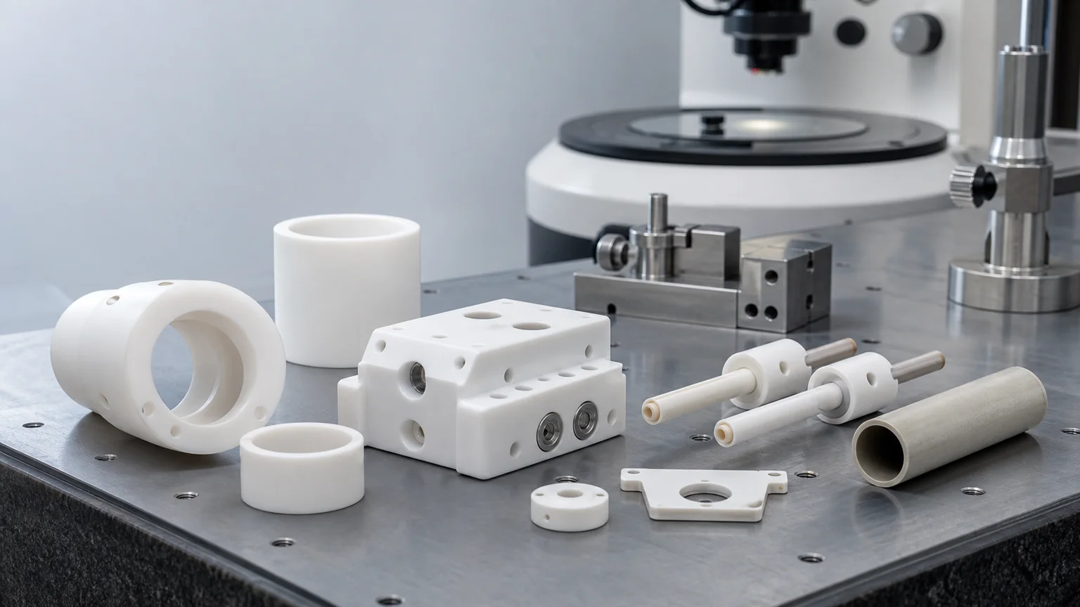
A ceramic fluid-path component should be quoted as part of the sample-contact system, not as a generic precision ceramic shape. The RFQ must identify every wetted surface, retained-volume risk, sealing interface, material grade, cleaning boundary, and customer system test before feasibility, price, tolerance, or timing can be confirmed.
This guide is limited to sample-contact and wetted-path ceramic components: needles, plungers, pistons, stators and rotors, metering-valve parts, flow cells, micro-nozzles, and orifice inserts. Dry-side sensor mounts, insulating housings, and general measurement fixtures belong in the broader sensor and measurement ceramic components guide. Cleanroom handling and incoming packaging are covered more broadly in the cleanroom and high-purity ceramic components guide.
The primary sourcing question here is narrower:
What must the drawing and RFQ define so a ceramic fluid-path part can be reviewed for carryover risk, dead volume, chemical exposure, sealing, cleaning, and measurable acceptance?
Why Analytical Fluid-Path Parts Need Their Own RFQ Logic
Current sources show continuing analytical-equipment activity: a 2025 Agilent LC mass-detection launch, EPA Method 8327, 2025 FDA laboratory methods, and ongoing NIH S10 instrumentation programs. They do not show that every instrument contains a custom ceramic fluid-path part.
The component evidence is narrower. Kyocera lists ceramic needles, cylinders, pistons, stators, metering valves, sapphire cells, and analyzer parts in its analytics, metrology, and laboratory product family. This supports reviewing ceramics where a defined sample path needs wear resistance, a smooth working surface, isolation, or resistance to a known medium—not assuming ceramic is automatically clean, inert, or suitable.
Component Families And Their Hidden Interfaces
The component name is only the start of the RFQ. The same nominal part can control very different functions in two instruments.
| Fluid-path component | What it may control | Hidden variable that changes the review |
|---|---|---|
| Sampling needle or probe | Sample pickup, transfer, wash, and positioning | Bore continuity, tip geometry, retained liquid, OD-to-ID relationship, wash access |
| Plunger or piston | Metered displacement and repeated sliding motion | Working diameter, straightness, counterface, seal preload, stroke, lubrication or dry-running condition |
| Stator or rotor | Port switching and fluid routing | Port registration, sealing bands, face condition, rotational datum, particle generation |
| Metering-valve insert | Flow control, shutoff, or dosing | Seat geometry, media, pressure direction, actuation load, customer leak test |
| Flow cell | Defined sample volume around an optical or sensing zone | Cavity geometry, window or sensor interface, seals, drainability, trapped volume |
| Micro-nozzle or orifice | Aspiration, dispensing, restriction, or wash flow | Bore diameter and length, taper, outlet edge, blockage risk, flow-test boundary |
For pump-like plungers, valve elements, and wetted metering hardware, the ceramic pump and valve component guide provides the wider fluid-control context. This page owns the analytical-instrument decision: how sample integrity and repeated wash cycles change the drawing, cleaning, and acceptance plan.
Material Purity, Sample Contamination, And Clean Packaging Are Different Claims
The phrase “high purity” is too ambiguous for an analytical-instrument RFQ. It can refer to three separate requirements that need separate evidence.
| Requirement | What it actually describes | Useful RFQ input | What it does not prove |
|---|---|---|---|
| Ceramic material purity | Nominal composition, grade, additives, trace constituents, and blank source | Exact supplier grade, composition certificate, lot-traceability requirement | Low carryover or compatibility with the sample method |
| Sample contamination control | Whether the finished part adds ions, particles, adsorbed material, or cross-sample residue under defined use | Sample chemistry, exposure time, temperature, wash sequence, contamination limit, validation method | That a nominally high-purity grade is clean after machining and handling |
| Clean packaging | Condition in which the finished part arrives for assembly | Cleaning scope, allowed residues, drying, individual separation, bagging, labels, opening environment | Analytical cleanliness after customer assembly, priming, calibration, or use |
A 99% or 99.5% nominal oxide statement, for example, is a material-composition statement only when supported by the grade documentation. It is not a sample-purity result. Likewise, a part delivered in a clean bag has not automatically passed a carryover, extractables, leachables, particle, or analytical-method validation.
The RFQ should use separate fields for material grade, sample-contact contamination limits, supplier cleaning, packaging, and final customer qualification. Combining them under one note such as “high-purity ceramic, laboratory clean” creates an acceptance dispute rather than a specification.
Carryover Is A Surface-And-Geometry Problem
Carryover occurs when material associated with one sample affects a later sample. A ceramic material name alone cannot control it. Retention can occur at rough internal surfaces, pores, scratches, blind intersections, abrupt diameter changes, seal gaps, poorly drained cavities, or interfaces that the wash flow does not reach.
Kyocera’s ceramic needle case study reports a zirconia needle with an internal surface roughness of Ra 0.1 micrometers or less in that supplier’s example and describes reduced influence from residual liquid. That number is a Kyocera product example based on its own measurements. It is not a CERAMIC CNC capability, a universal requirement for analytical needles, or proof that a different geometry will meet a customer’s carryover limit.
A useful carryover review asks:
- Which internal and external zones contact the sample, reagent, rinse, or calibration fluid?
- Does the flow reverse, pulse, dwell, or stop inside the component?
- Are there diameter steps, side ports, blind pockets, intersecting holes, threads, adhesive gaps, or seal crevices?
- Which surfaces can be reached by dimensional or roughness measurement?
- What wash sequence, sample chemistry, concentration range, and detection method define the customer’s carryover test?
Where the critical feature is a small or deep bore, use the ceramic micro-hole machining RFQ guide to define diameter, depth, taper, entry and exit condition, cleaning access, and inspection method. Do not specify a very low Ra on an inaccessible bore unless the measurement route and acceptance method are also defined.
Dead Volume Must Be Controlled Across The Assembly
Dead volume is not just the calculated cavity inside the ceramic body. It can also appear between the ceramic and a tube, around a seal, behind a valve face, at a misregistered port, or where a bore does not meet an intersecting feature as intended.
The drawing should distinguish:
- The intended swept or flushed volume.
- Any permitted static cavity.
- Seal compression zones and gaps after assembly.
- Port-to-port alignment at each valve position.
- Bore and counterbore transitions.
- Corners or pockets that cannot drain in the installed orientation.
For a rotor/stator pair, port location and sealing-band geometry may matter more than a globally tight outside profile. For a needle, the relationship among the bore axis, guide diameter, and tip may matter more than an isolated OD tolerance. For a flow cell, the system volume depends on windows, seals, fittings, and assembly preload as well as the ceramic cavity.
Dead-volume acceptance therefore needs two levels. The ceramic supplier can review and inspect the dimensions assigned to the ceramic part. The equipment owner must validate the assembled flow path, because the ceramic dimensional report cannot prove purge efficiency, response time, dispersion, or the final internal volume after assembly.
Metal-Ion Contamination Is A Test Boundary, Not A Marketing Claim
Replacing a metal with ceramic removes one metal surface from the path; it does not establish zero contamination. A ceramic grade may contain sintering additives or trace constituents, while grinding, lapping, cleaning, fixtures, seals, adhesives, packaging, and mating parts can add other residues. Kyocera’s liquid-analysis example says zirconia addressed metal elution in that application, but the same source warns that chemical resistance depends on the liquid and operating conditions.
The RFQ should name the elements or substances of concern, all sample and cleaning chemistries, concentration, temperature, exposure time, and whether the risk is extractables, leachables, particles, adsorption, corrosion products, or cross-sample residue. The customer should also define its blank, rinse, elemental, chromatography, or other validation method. Material certificates, lot identity, and declared supplier cleaning can support that work; they do not replace method-specific qualification.
Material Direction Starts With The Wetted Medium
No single ceramic is the default for every analytical fluid path. The initial comparison should use exact service conditions and supplier-grade data, not a generic property table.
| Material direction | Why it may enter the review | Questions to resolve before selection |
|---|---|---|
| Zirconia | Smooth precision needles, plungers, valve elements, and wear interfaces where strength and repeated contact matter | Exact grade and additives, media compatibility, hydrothermal or temperature conditions, surface finish, counterface |
| Alumina | Stators, rotors, valve parts, insulating wetted components, and structural flow-path bodies | Purity grade, porosity, media, lapping and edge needs, trace-element concern, sealing or metallization interface |
| Sapphire | Transparent cells, windows, or optical-contact zones | Optical path, crystal orientation if relevant, joining route, seal stress, surface quality, customer optical qualification |
| Silicon nitride or silicon carbide | Selected wear, thermal, or chemically demanding mechanisms | Exact grade, sample chemistry, load path, finish, counterface, electrical or optical constraints |
For zirconia parts, the zirconia machining and design guide explains why grade, geometry, grinding route, and inspection must be reviewed together. A material that performs well as a plunger may be unnecessary for a static flow-cell body. A chemically resistant bulk material may still be unsuitable if its grade, surface condition, or joining material interferes with the analytical method.
The material decision should be recorded by supplier grade or an approved equivalent process, fired state, blank source requirements, lot documentation, and the functional reason for selection. “White ceramic,” “laboratory ceramic,” or “high-purity ceramic” is not enough for quotation.
Bore, Concentricity, And Sealing Interfaces Need A Datum Plan
Analytical fluid-path parts frequently combine features that are difficult to relate after sintering and hard finishing. A drawing should establish the functional hierarchy rather than applying the tightest tolerance to every surface.
| Functional relationship | Why it matters | Possible evidence to discuss |
|---|---|---|
| Bore axis to guide OD | Positions a needle or nozzle relative to a mating guide | Method appropriate to bore access, length, and part size |
| Tip or outlet to bore axis | Affects aspiration, dispensing, spray, or target alignment | Optical or dimensional inspection with an agreed datum setup |
| Sealing face to bore or port | Controls interface position and possible crevice volume | Flatness/profile, perpendicularity, and port-location evidence as specified |
| Rotor ports to rotational datum | Controls valve registration at each indexed position | CMM, optical, fixture, or customer gauge method agreed before production |
| Plunger working OD to end features | Controls guided motion and seal relationship | Diameter, form, runout, and surface evidence on named working zones |
The measurement method is part of the specification. A short accessible bore, a long micro-bore, and an intersecting internal channel do not support the same inspection method. Feasibility also depends on grade, blank route, part size, aspect ratio, wall thickness, fixturing access, and the amount of material left for finishing. No general tolerance or concentricity promise should be inferred from this article.
Finish Only The Surfaces That Control Function
A part may contain a wetted bore, sliding plunger OD, lapped valve band, non-contact face, and bonded or gasketed interface. One low roughness value over the entire part can add risk without improving function. Name each functional zone, justify its texture or form, and state how it will be measured. The ceramic surface finish and subsurface damage guide explains why Ra alone does not prove freedom from pull-out, microcracks, debris, or edge damage.
For lapped valve faces, define the working band, interruptions, edge condition, form requirement, and post-lap cleaning. For bores, confirm that the requested finish is measurable at depth. For plungers, define the counterface, stroke, load, medium, and working finish.
Machining Route Depends On Blank State And Feature Sequence
The quotation should identify whether the part starts from a near-net blank, tube, rod, plate, or customer-specified blank and which features are created before or after firing. Blank route and feature sequence affect distortion allowance, material removal, fixturing, surface integrity, and whether bores, ports, faces, and edges remain accessible. Green machining may establish bulk geometry; post-sinter diamond grinding, lapping, honing, or polishing may be reviewed for named functional zones. A micro-nozzle, lapped stator, thin needle, and sapphire cell do not share one universal route, so the drawing, grade, quantity, access, and inspection plan must be reviewed together.
Media Compatibility Must Be Defined By Conditions
“Chemical resistant” is not complete. Compatibility can change with grade, reagent, pH, concentration, temperature, time, pressure, cleaning agent, drying, and thermal cycle; seals, metals, polymers, brazes, or adhesives may be limiting even when the ceramic is stable. State normal and cleaning exposure, including wet shutdown or dried residue. Supplier data can screen candidates, but only customer testing can qualify method-specific extraction, corrosion, adsorption, carryover, and lifetime. CERAMIC CNC should not confirm compatibility from a material family name alone.
Cleaning Verification And Packaging Need Separate Acceptance Gates
Cleaning language should identify the delivered condition, not rely on terms such as “ultraclean” or “laboratory clean.” Before quotation, define:
- Which surfaces are wetted and which are protected from contact.
- Allowed and prohibited cleaning agents.
- Rinse-water or solvent requirements, if any.
- Drying method and whether trapped liquid is possible.
- Handling controls after cleaning.
- Individual separation of tips, lapped faces, and sealing lands.
- Bagging, tray, label, lot, and opening-environment requirements.
- Whether the customer performs final cleaning after assembly.
The supplier-side evidence may be a declared process record, visual inspection, agreed residue test, or customer-defined witness method when included in scope. The customer-side evidence may involve assembled-system blanks, rinse tests, carryover sequences, particle checks, or method validation. These are not interchangeable.
For broader incoming-condition decisions, use the cleanroom and high-purity guide. For this analytical page, the decisive question is whether the cleaning and package protect the sample-contact zones until the customer takes control.
Inspection Evidence Should Match The Failure Mode
An analytical fluid-path part does not need the maximum report package on every surface. It needs evidence tied to the feature that could invalidate assembly or customer testing.
| Risk | Supplier evidence to define in the RFQ | Customer-level qualification that remains separate |
|---|---|---|
| Bore restriction or mislocation | Named bore dimensions, datum relationship, optical review where accessible | Flow, aspiration, dispensing, or pressure response in the installed system |
| Retention or carryover risk | Accessible roughness evidence, geometry inspection, cleaning record if specified | Method-specific blank and carryover sequence |
| Seal leakage | Ceramic sealing-land form, finish, edge, and port-position evidence | Leak or pressure test with actual seal, preload, media, and assembly |
| Material contamination concern | Grade certificate, lot identity, agreed supplier-cleaning evidence | Extractables, leachables, elemental, adsorption, or sample-recovery test |
| Chipping or particle risk | Magnified edge and tip inspection to agreed zones and criteria | Particle performance after assembly, actuation, and service cycling |
| Rotor/stator registration | Port and datum measurement, matched-set identification if required | Switching, life, torque, and cross-port leakage in the valve assembly |
Inspection methods must be selected before machining commitments are made. Deep internal features may not be directly measurable with the same method as external datums. If the buyer requires flow, leak, pressure, volume, or carryover testing, the RFQ must state the test fluid, fixture, pressure or flow condition, sequence, sampling plan, and acceptance limit. Otherwise those tests remain customer system qualifications.
Supplier Review And Customer Qualification Are Different Decisions
The ceramic supplier can review grade, blank route, geometry, machining access, edge risk, named dimensions, accessible texture, agreed cleaning, and package evidence when those items are in scope. The equipment owner must qualify the assembled seals, dead volume, fluid behavior, carryover, adsorption, corrosion, extractables, calibration, response, repeatability, and service life under the real method conditions.
This boundary is especially important for medical-adjacent analyzers. A dimensionally accepted ceramic component is not a cleared medical device, does not establish clinical performance, and does not validate the customer’s analytical method.
RFQ Checklist For Analytical-Instrument Ceramic Fluid Paths
Before requesting a quotation, provide:
- 2D drawing and STEP/CAD file with revision status.
- Component function: needle, plunger, piston, stator, rotor, metering-valve part, flow cell, nozzle, or orifice.
- Exact wetted surfaces and normal flow direction.
- Approved material grade, purity requirement, fired state, and blank-source restriction, or the conditions needed to review them.
- Sample, reagent, solvent, wash, calibration, and cleaning chemistry.
- Temperature, pressure, vacuum if relevant, exposure time, dwell, stroke, cycle, and storage condition.
- Bore, port, cavity, tip, sealing land, sliding face, and datum relationships.
- Carryover, dead-volume, metal-ion, particle, adsorption, or extractables concern.
- Surface texture, form, and edge criteria only on functional zones.
- Mating tube, seal, valve, window, sensor, counterface, and assembly-preload information.
- Supplier inspection method, report, material certificate, and sampling requirements.
- Supplier cleaning, final customer cleaning, packaging, lot marking, and protected-face requirements.
- Prototype and production quantities, target timing, and change-control expectations.
- Customer-owned flow, leak, pressure, carryover, chemical, analytical, life, and regulatory qualification tests.
The broader custom ceramic machining RFQ checklist helps organize the drawing, material, quantity, inspection, and packaging package. The automation, vacuum, optical, and instrument ceramic application hub provides the wider path for sensor supports, metrology parts, vacuum hardware, cleanroom components, and laboratory assemblies.
Practical Takeaway
The correct reason to create an analytical-instrument ceramic fluid-path RFQ is not simply that ceramics are hard, clean, or chemically resistant. It is that a defined sample-contact interface has a measurable problem involving retention, wear, contamination, electrical isolation, sealing, or geometry.
Start with the sample path and failure mode. Separate material purity from sample contamination control and delivered cleanliness. Name the wetted surfaces, dead-volume risks, media, datums, sealing zones, finish requirements, cleaning boundary, inspection evidence, and customer system tests. Then send the drawing and application conditions through the site’s RFQ path for engineering review before feasibility, price, tolerance, or timing is confirmed.
FAQ
Does a high-purity ceramic grade guarantee low analytical carryover?
No. Material composition is only one input. Carryover also depends on surface condition, pores or damage, internal geometry, seal gaps, wash access, sample chemistry, cleaning, assembly, and the customer’s analytical method.
Is zirconia always the best material for a ceramic sampling needle?
No. Zirconia is a credible direction for selected smooth, wear-resistant needle and plunger applications, but the exact grade, medium, temperature, geometry, finish, and customer validation determine suitability. Alumina, sapphire, or another ceramic may fit a different function.
Can a dimensional report prove a flow cell or metering valve will work?
No. It can verify specified ceramic features. Final dead volume, leakage, flow, switching, optical response, carryover, and analytical performance depend on the complete assembly and customer test conditions.
- Analytical instruments
- Ceramic fluid path components
- Zirconia
- Micro holes
- Contamination control
- Inspection
- RFQ checklist