Published · CERAMIC CNC Engineering · Engineering Guide · 14 min read
Machined Alumina Components for High- and Ultra-High-Vacuum Systems
RFQ guide for dense machined alumina rings, sleeves, supports, standoffs, liners, and isolator bodies, covering trapped volumes, cleaning, joining interfaces, packaging, and leak-test ownership.
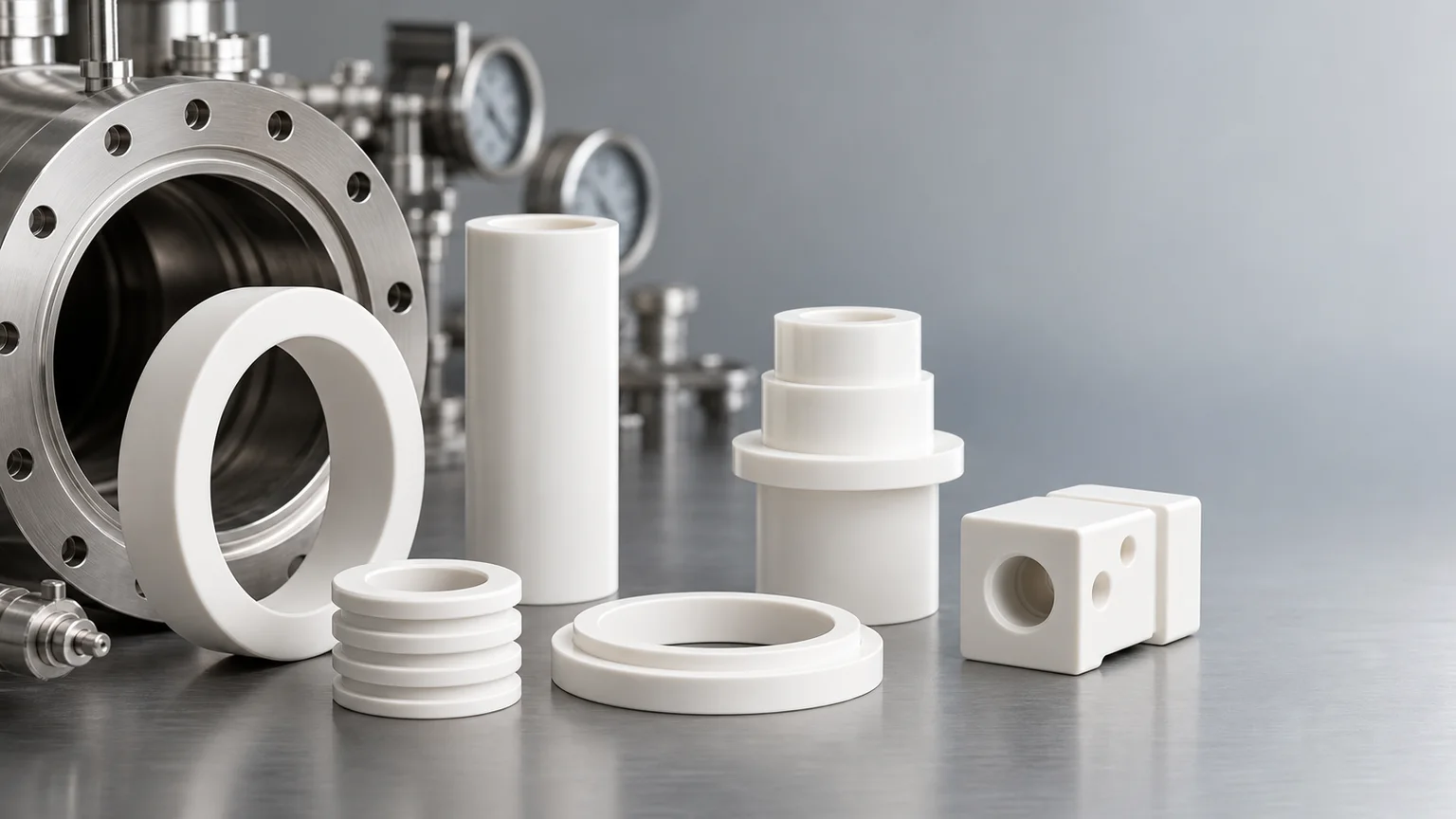
A machined alumina body is not automatically a high-vacuum or ultra-high-vacuum qualified component. The RFQ must define the exact dense alumina grade, vacuum-side geometry, pressure and bake context, process gas, cleaning and packaging requirements, metallization or joining interfaces, and who owns final leak testing. Qualification belongs to the completed assembly and test plan, not to the ceramic material name alone.
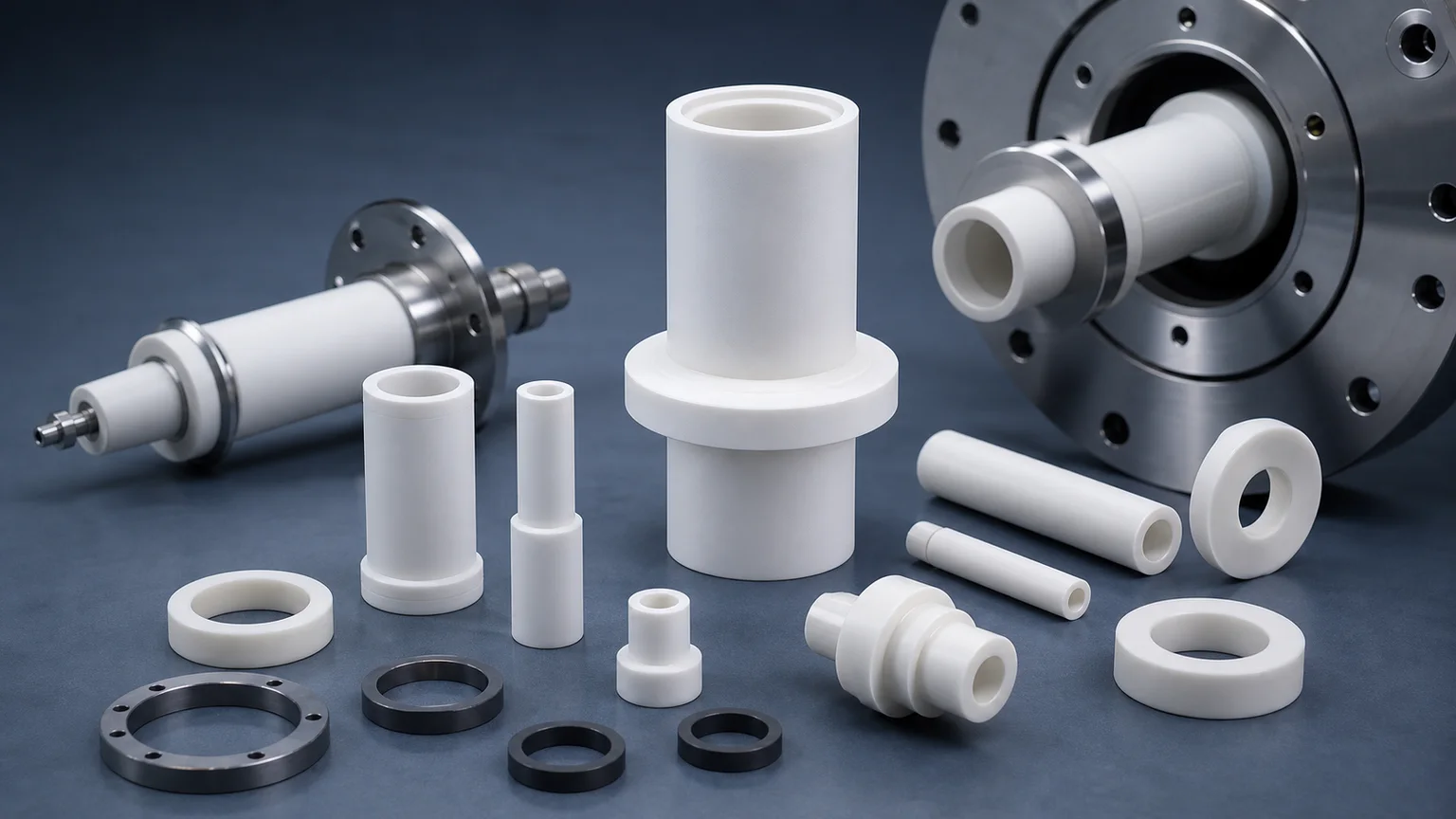
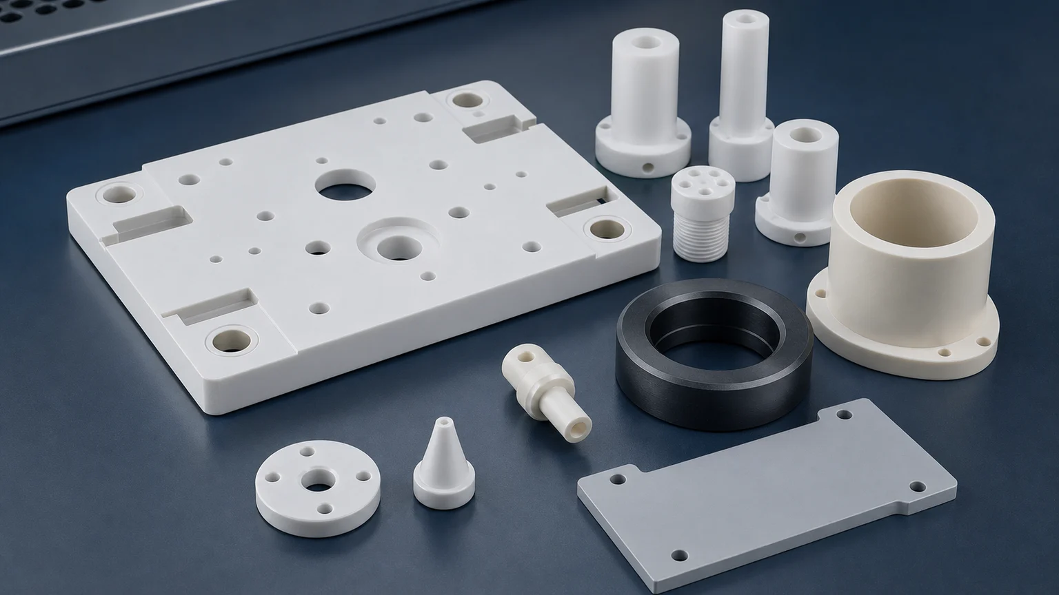
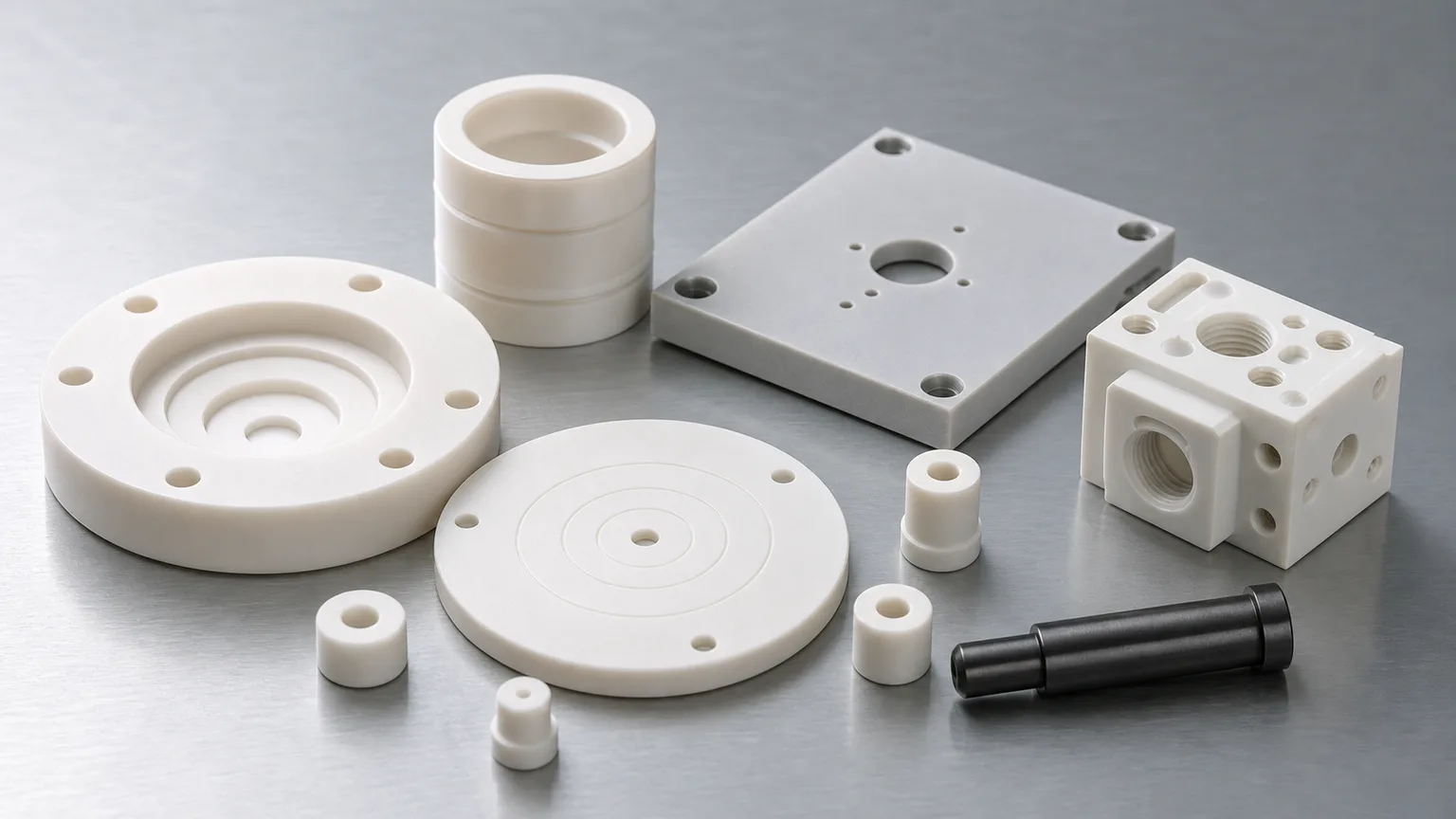
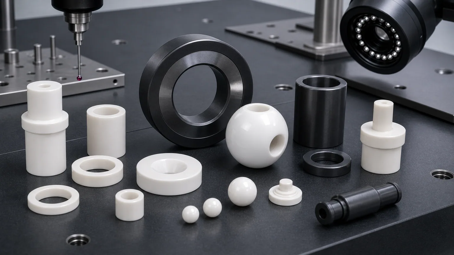
This guide covers non-chuck, vacuum-side alumina bodies: spacers, rings, sleeves, supports, standoffs, liners, shields, and isolator bodies that locate, separate, protect, or electrically isolate hardware inside or adjacent to a vacuum system. These parts appear in analytical instruments, deposition and etch equipment, beam-line and accelerator hardware, scientific chambers, mass-spectrometry systems, sensor assemblies, and vacuum process tools.
The commercial signal is durable. In its July 14, 2026 mid-year forecast, SEMI projected 2026 wafer-fab-equipment sales of $143.9 billion. That forecast supports continued equipment investment, but it does not define a ceramic specification. A useful sourcing page must still convert the application into material, geometry, cleanliness, joining, and acceptance decisions.
Use the automation, optics, vacuum, and instrument ceramic application hub for the wider component pathway. Use this page when the primary task is preparing an RFQ for a dense alumina body exposed to, or installed next to, a high- or ultra-high-vacuum volume.
Keep This Page Separate From Feedthrough And Vacuum-Chuck RFQs
Several vacuum-related ceramic searches describe different buyer tasks. Combining them creates an under-specified quote.
| Dominant sourcing task | Component examples | Page that owns the decision |
|---|---|---|
| Non-chuck vacuum-side support, spacing, isolation, or shielding | Dense alumina spacer, ring, sleeve, support, standoff, liner, isolator body | This guide |
| Conductor, pin, signal, or power path across a vacuum/electrical boundary | Ceramic sleeve, sealing shoulder, feedthrough body, ceramic-to-metal interface | Ceramic feedthrough insulator guide |
| Wafer or substrate holding by suction | Dense or porous chuck, suction plate, groove field, hole field, working face | Ceramic vacuum chuck flatness guide |
| Voltage-driven creepage, clearance, field relief, or conductor spacing | Standoff, bushing, insulating support, ribbed body | High-voltage ceramic insulator RFQ guide |
A support ring can be electrically insulating without being a feedthrough. A liner can face process gas without distributing that gas. A spacer can sit under vacuum without being a hermetic seal. A flat support plate can be vacuum-side hardware without functioning as a chuck. State the function first; do not let the word “vacuum” select the wrong article or inspection plan.
The Product Boundary: Ceramic Body Versus Qualified Assembly
The most important scope statement is simple:
A dimensionally accepted ceramic body does not prove final chamber pressure, pump-down time, hermeticity, electrical performance, or bake-cycle survival.
Kyocera’s ultra-high-vacuum component overview describes an integrated route that includes fine-ceramic manufacture, metallization, plating, brazing, welding, and helium leak testing. CeramTec’s hermetically sealed component overview likewise treats ceramic-to-metal joining and leak testing as part of a complete assembly program. These are useful boundary examples: their finished-product specifications belong to their materials, joint designs, process controls, and test conditions.
They are not transferable capability claims for a separately machined alumina body. Do not copy a third-party leak rate, bake temperature, voltage, pressure rating, cleanliness level, or lifetime into a ceramic machining RFQ and assume the body alone will deliver it.
Define the requested deliverable as one of the following:
- Machined alumina body with dimensional and visual inspection.
- Cleaned and specially packaged machined alumina body.
- Alumina body prepared to a joining supplier’s metallization specification.
- Metallized ceramic body, only when the coating system and responsibility are explicitly included.
- Joined ceramic-to-metal subassembly with a defined test plan.
- Fully qualified vacuum assembly, including all hardware, joining, cleaning, bake, and leak-test requirements.
If the RFQ stops at item 1 or 2, final UHV qualification remains outside the ceramic-body acceptance boundary.
Specify A Dense Alumina Grade, Not “Alumina”
Alumina is often selected for vacuum-side supports because it can combine electrical insulation, hardness, dimensional stability, and chemical resistance. The word “alumina,” however, covers multiple compositions and manufacturing routes. Review the precision machined alumina parts guide before releasing the drawing.
A quote-ready material note should address:
- Manufacturer and exact grade or an approved-equivalent rule.
- Nominal alumina content and the significance of sintering additives for the process environment.
- Dense, fully fired state; do not substitute a porous ceramic without a separate gas-load and functional review.
- Blank route, available stock, near-net geometry, and whether the customer controls the blank source.
- Certificate, lot traceability, color, surface condition, or material-property documentation if required.
- Process-gas, plasma, chemical-cleaning, radiation, and bake exposure that the system owner expects the grade to tolerate.
- Whether later metallization, plating, brazing, adhesive bonding, coating, or welding to attached hardware constrains the grade.
Nominal purity is not a stand-alone vacuum qualification. Density, open porosity, surface history, finishing residue, handling, attached materials, and the complete assembly can affect gas load or pump-down behavior. Kurt J. Lesker’s basic outgassing discussion notes that every surface outgasses and identifies porous ceramics, polymers, lubricants, and human contamination as important concerns. That is why this guide focuses on dense alumina and controlled post-machining handling, while still requiring system-level validation.
Match The Component Family To Its Functional Surfaces
The drawing should identify why each face, bore, edge, or pocket exists.
| Component family | Vacuum-side function | Geometry that commonly controls the RFQ | Acceptance question |
|---|---|---|---|
| Spacer or washer | Establish stack height or separate metal parts | End faces, thickness, parallelism, bore clearance, vent path | Does the installed stack leave an unvented annulus or bolt pocket? |
| Ring or collar | Locate a tube, shield, electrode, sensor, or liner | ID/OD relationship, end-face squareness, split or vent feature, edge condition | Which diameter is the datum, and can gas escape from the enclosed interface? |
| Sleeve | Isolate or guide a shaft, tube, probe, or fastener | Bore size, straightness, wall thickness, concentricity, lead-in | Is the annular space open to pumping, or does the sleeve trap a volume? |
| Support or standoff | Carry a controlled load while isolating hardware | Mounting pads, hole position, end-face parallelism, fillets, edge radius | What preload, mating material, temperature cycle, and voltage context apply? |
| Liner or shield body | Separate process-facing hardware from a chamber or source | Process-facing surface, slots, ports, mounting details, cleanability | Which surfaces see gas, plasma, deposition, cleaning, or particle limits? |
| Isolator body | Provide a ceramic structure for later joining or assembly | Metallization bands, sealing shoulders, coaxial features, joint transitions | Is the deliverable ceramic-only, metallization-ready, joined, or leak-tested? |
Do not apply the tightest tolerance or finish to every surface. Mark vacuum-facing, sealing, locating, joining, process-facing, electrically stressed, and non-functional zones separately. The datum strategy should follow the installed function and a physically repeatable inspection setup.
Blind Holes, Threads, Recesses, And Trapped Volumes
In vacuum hardware, a geometry that is harmless at atmosphere can extend pump-down or imitate a leak. Pfeiffer’s UHV chamber design guidance advises minimizing blind holes and trapped geometry and explains that enclosed spaces can create virtual-leak behavior. Apply that principle to the ceramic part and its mating hardware, not only to the chamber wall.
Blind holes
A blind mounting hole can trap gas below a screw, pin, or insert. The RFQ should show thread depth, usable engagement, bottom relief, mating fastener, and whether a vent path is required. Do not add a small vent hole casually: it can become a fragile machining feature, a process-gas path, or a cleaning trap. The system designer must define where the vent connects and what it is allowed to expose.
Internal ceramic threads
Threads add root geometry, chip-sensitive crests, inspection difficulty, cleaning difficulty, and potential dead volume. State thread standard, class or fit intent, engagement length, runout, lead-in, mating fastener, torque or preload, and whether the hole is through or blind. Review whether a clearance bore, external clamp, vented fastener, or separately qualified insert provides a lower-risk assembly. Thread feasibility depends on grade, diameter, pitch, wall section, blank route, and inspection method; it is not a catalog guarantee.
Counterbores and recesses
Annular recesses can trap gas behind washers, shoulders, flanges, or nested parts. Define the assembled cross-section, not just the isolated ceramic model. Include corner radii, relief grooves, surface finish, cleaning access, and the intended pump path.
Intersecting passages and micro-features
Small vent holes, orifices, and intersecting passages need diameter, depth, aspect ratio, entry and exit condition, position, blockage review, and cleaning access. Use the ceramic micro-hole machining RFQ guide when the feature is primarily a small hole. Use the precision ceramic nozzle guide when the geometry meters, directs, or shapes process gas. A vent is not automatically a nozzle, and a liner is not automatically a gas-distribution component.
Pressure, Bake, Process Gas, And Cleaning Are Drawing Inputs
“For UHV” is not enough information to quote the body. Provide the operating and acceptance context.
| System input | Why the machining review needs it | What to place in the RFQ |
|---|---|---|
| Pressure regime and pump-down objective | Determines sensitivity to trapped volume, gas load, rough surfaces, residue, and attached materials | Target operating regime, acceptable pump-down behavior, pressure differential, and system-test owner |
| Bake schedule | Changes thermal expansion, desorption, joint stress, and packaging or coating choices | Maximum and minimum temperature, ramp, dwell, cycles, atmosphere, support condition, and whether testing occurs before or after bake |
| Process gas or chemistry | Can change material-grade, surface, cleaning, and contamination decisions | Gas species, pressure range, plasma or reactive exposure, condensable films, and prohibited materials |
| Thermal and mechanical load | Affects standoff geometry, contact stress, joint transition, and datum stability | Mating materials, preload, fastener method, thermal gradients, shock or vibration, and allowed movement |
| Cleaning and handling | Determines allowable residue, edge protection, recleaning, and packaging | Approved and prohibited chemistries, ultrasonic permission, rinse/dry method, gloves, bagging, and opening environment |
Lesker explains that outgassing depends on surface composition, vacuum history, and temperature, and that pumping and bake history can change observed gas load. Its high-vacuum cleaning guidance also emphasizes contamination from machining fluids, human handling, and storage. These principles support an application-specific cleaning plan; they do not justify a universal recipe or a cleanliness claim without verification.
For particle-sensitive parts, connect the RFQ to the cleanroom and high-purity ceramic component guide. State the customer’s incoming standard, not an assumed cleanroom class.
Machining Route And Datum Planning
The manufacturing route depends on grade, blank availability, size, geometry, material allowance, quantity, and functional zones. A near-net or green-machined blank may reduce hard finishing, while critical bores, faces, thicknesses, and joining surfaces may still require post-sinter diamond grinding, lapping, or another reviewed finishing route.
Useful drawing practices include:
- Establish one primary datum from a stable mounting, sealing, or locating surface.
- Relate bores, IDs, ODs, and shoulders to the datum that matters after assembly.
- Define free-state or supported measurement when a thin ring or liner can distort under fixturing.
- Identify lapped or low-roughness faces individually rather than applying a global finish note.
- Define edge breaks and maximum chips by functional zone, especially around bores, vent holes, metallization bands, and sealing lands.
- Show inspection access; a tolerance that cannot be measured reproducibly is not a useful acceptance requirement.
- Provide the mating cross-section for nested parts, blind fasteners, hidden recesses, and potential trapped volumes.
Thin rings, long sleeves, deep bores, interrupted walls, and asymmetric liners can require different blank and fixture strategies even when they use the same alumina grade. Final tolerance and lead time must follow drawing review rather than a generic material capability table.
Metallization-Ready Does Not Mean Metallized Or Hermetic
A “metallization-ready” alumina surface is a ceramic feature prepared to a downstream supplier’s controlled input specification. It is not proof that metallization will adhere, that the braze joint will survive bake cycles, or that the final assembly will pass a leak test.
Before machining, obtain the joining supplier’s requirements for:
- Alumina grade and approved blank source.
- Metallized-zone width, length, location, masking boundary, and edge setback.
- Required surface condition, texture, cleanliness, and prohibited contamination.
- Dimensional allowance for metallization, plating, braze, or final grinding.
- Joint transition radii, ceramic wall section, metal geometry, and thermal-expansion analysis owner.
- Handling and packaging between ceramic finishing, metallization, plating, and brazing.
- Witness coupons, destructive samples, lot qualification, and documentation if required.
The drawing should distinguish ceramic-body dimensions from final assembly dimensions. If a metal flange, tube, pin, or cap is supplied by another party, identify who controls its material, tolerances, cleaning, and joining condition.
Assign Joining And Leak-Test Responsibility Before Quotation
Leak testing cannot be reduced to the phrase “helium leak tight.” ISO 20485:2017 covers tracer-gas leak-testing techniques, while Pfeiffer’s leak-detection application guidance shows that pressure direction, test pressure, fluid reference, localization versus quantification, calibration, and the maximum acceptable leak rate must be defined before selecting the method.
Use a responsibility matrix:
| Deliverable or test | Required definition | Typical responsibility boundary to confirm |
|---|---|---|
| Machined ceramic body | Grade, dimensions, datums, surface zones, edge criteria | Ceramic machining scope |
| Metallization-ready surface | Downstream specification, masking, texture, cleanliness, allowance | Jointly approved by ceramic and metallization suppliers |
| Metallization and plating | Process, thickness, coverage, adhesion evidence, handling | Metallization supplier unless explicitly included |
| Ceramic-to-metal joint | Metal grade, joint design, braze or sealing route, thermal cycle | Assembly or hermetics supplier |
| Cleaning and bake | Sequence, chemistry, atmosphere, supports, recontamination controls | Owner must be named at each process stage |
| Tracer-gas or other leak test | Test object, method, direction, pressure, tracer, calibration, limit, report | Assembly supplier, system integrator, or customer as contracted |
| Final high/UHV qualification | Chamber configuration, pumps, seals, attached hardware, process condition, acceptance evidence | System owner or qualified assembly integrator |
No leak-rate number in another manufacturer’s catalog should be reused as CERAMIC CNC’s acceptance limit. The buyer must state the applicable limit and method; the quotation must state whether that test is included.
Cleaning And Packaging Must Protect The Vacuum-Side State
Cleaning after hard machining should remove the agreed process residues without damaging the alumina, fine edges, threads, metallization-ready zones, or any supplied coating. The approved sequence depends on the exact grade and later process. Clarify whether ultrasonic cleaning is allowed, which solvents or detergents are prohibited, the rinse-water requirement, drying method, final inspection, and whether the customer will reclean or bake the part.
Packaging should preserve the accepted state:
- Protect lapped faces, seal shoulders, bore entries, and thin edges from contact.
- Keep parts separated in clean trays or individual compartments.
- Cap or shield critical bores only with an approved, non-shedding method.
- Define single or double bagging, bag material, labeling, and opening environment when required.
- State whether parts ship before or after metallization, cleaning, bake, or leak test.
- Avoid unapproved foam, adhesive labels, lubricants, corrosion inhibitors, or paper in direct contact with vacuum-facing surfaces.
A dimensional report issued before an uncontrolled cleaning or packing step does not prove the received part is ready for vacuum assembly.
Inspection Evidence Should Follow The Failure Mode
| Risk | Evidence to discuss | Boundary |
|---|---|---|
| Wrong or inconsistent material | Certificate, grade designation, lot or blank traceability | Confirms supplied material documentation, not system performance |
| Stack or alignment error | Thickness, parallelism, bore/OD relationship, CMM or agreed gauges | Use functional datums and installed orientation |
| Edge chips or cracks | Zone-specific visual standard, magnification, images if required | Define permitted zones and acceptance size on the drawing |
| Trapped or blocked feature | Cross-section review, vent-path dimensions, optical inspection, blockage check | Does not replace assembled pump-down evaluation |
| Joining-surface mismatch | Metallization-zone dimensions, texture or roughness method, cleanliness record | Downstream supplier must approve the input specification |
| Surface residue or particles | Cleaning record, handling statement, protected packaging, customer incoming test | No universal particle or outgassing claim without a method |
| Assembly leakage | Defined tracer-gas or other functional test and report | Belongs to the joined assembly, not the bare ceramic body |
RFQ Checklist For High- And Ultra-High-Vacuum Alumina Bodies
Before requesting price or lead time, send:
- Revision-controlled 2D drawing and STEP or native CAD model.
- Part function: spacer, ring, sleeve, support, standoff, liner, shield, or isolator body.
- Exact dense alumina grade, blank source rule, fired state, certificate, and equivalency policy.
- Installed cross-section showing mating parts, seals, fasteners, hidden recesses, and vent paths.
- Vacuum regime, pressure differential, pump-down objective, process gas, plasma or chemical exposure, and system-test owner.
- Bake temperature range, ramp, dwell, cycle count, atmosphere, support, and whether acceptance occurs before or after bake.
- Functional datums, sealing or locating faces, bores, IDs/ODs, threads, blind holes, vent features, and trapped-volume controls.
- Tolerances, GD&T, surface finish, flatness, edge break, chip criteria, and measurement condition by functional zone.
- Metallization-ready, coating, joining, or ceramic-to-metal interface specification and downstream supplier approval.
- Cleaning, prohibited substances, ultrasonic permission, handling, bagging, trays, labels, and protected-surface requirements.
- Dimensional, material, visual, cleanliness, leak-test, and final qualification evidence, with an owner for each item.
- Quantity, prototype or production stage, target timing, repeat-order controls, and change-notification needs.
Use the custom ceramic CNC machining RFQ checklist to complete the general drawing, quantity, inspection, and commercial inputs. For a direct engineering review, submit the package through the RFQ page.
Practical Takeaway
Dense machined alumina can be a strong material direction for vacuum-side spacers, rings, sleeves, supports, standoffs, liners, and isolator bodies. The difficult part is not attaching the label “UHV.” It is controlling the actual grade, functional surfaces, datum relationships, blind features, threads, recesses, trapped volumes, process exposure, cleaning, packaging, metallization input, joining sequence, and test ownership.
Keep the boundaries explicit. The bare ceramic body can be accepted for material documentation, dimensions, surfaces, edges, cleaning, and packaging. The joined assembly must be accepted for joint integrity and leak performance. The complete vacuum system must be accepted for pressure, pump-down, bake, process, electrical, and lifetime requirements.
That separation gives procurement comparable quotations and prevents a third-party assembly specification from being misrepresented as a ceramic machining capability.
RFQ note: Final feasibility, tolerance, price, lead time, material route, surface condition, cleaning, packaging, metallization preparation, joining scope, leak testing, and high/UHV qualification depend on the reviewed drawing, exact alumina grade, blank state, assembly design, process environment, quantity, and agreed acceptance method.
- High vacuum systems
- Ultra high vacuum
- Alumina
- Vacuum side components
- Virtual leak risk
- Metallization ready surfaces
- Cleaning and packaging
- RFQ review