Published · CERAMIC CNC Engineering · Engineering Guide · 5 min read
Ceramic Vacuum Chuck RFQ Guide: Flatness, Hole Fields, Porous Surfaces
How to prepare an RFQ for ceramic vacuum chucks, porous ceramic chucks, suction plates, wafer support surfaces, flatness maps, hole fields, grooves, and inspection.
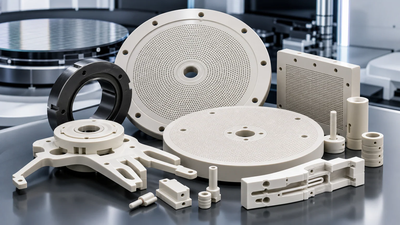
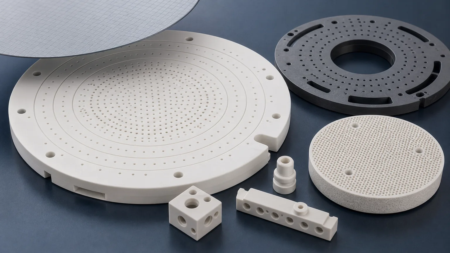
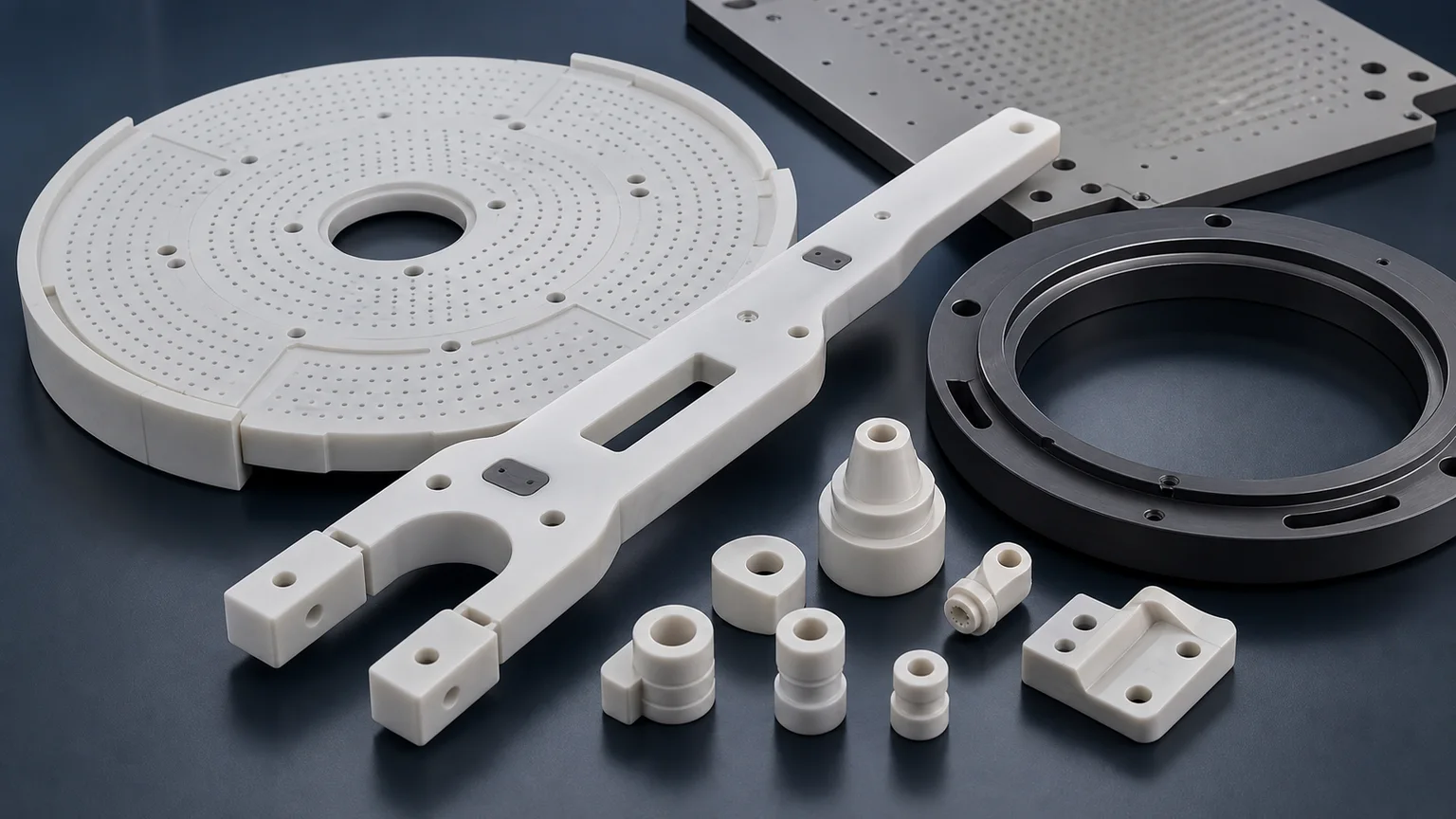
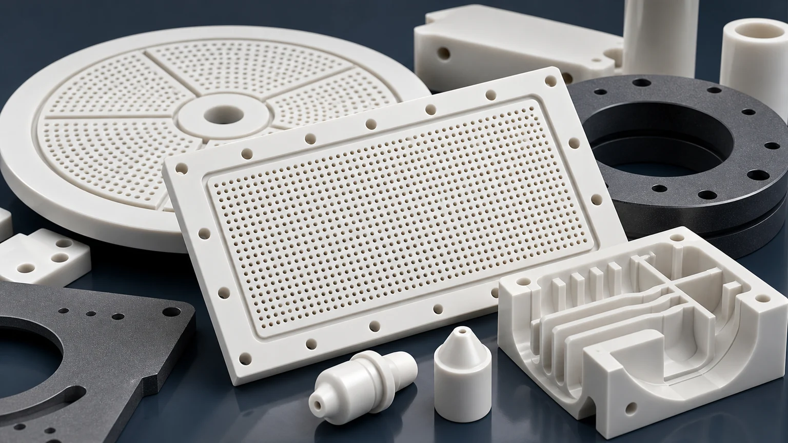
A ceramic vacuum chuck RFQ is not only a plate with holes. It is a flatness, suction distribution, datum, surface integrity, and cleaning problem. Send the drawing, CAD, material, hole or pore logic, groove layout, flatness requirement, support condition, and inspection method before expecting a useful quote.
Vacuum chucks and suction plates appear in wafer handling, inspection fixtures, precision positioning, electronics assembly, and clean manufacturing equipment. The ceramic material may be alumina, silicon carbide, porous ceramic, MACOR for prototypes, or another technical ceramic, but the material name alone does not define the quote.
For the broader semiconductor component context around wafer handling parts, chucks, SiC rings, AlN plates, gas parts, and inspection evidence, see the precision ceramic components for semiconductor equipment guide. For semiconductor tool chuck plates, porous inserts, SiC rings, manifold blocks, and component-level RFQs, use the machined ceramic vacuum chuck components guide.
The useful first question is:
What must the chuck prove in use: flatness, holding force, particle control, repeatability, or vacuum uniformity?
If that question is not answered, the supplier can machine a plate that matches the visible geometry but still fails the fixture.
Why This Needs A Dedicated RFQ
Existing ceramic articles cover semiconductor equipment and micro-holes, but vacuum chucks combine several risks in one part:
- The wafer-facing or part-facing surface may need flatness across a large area.
- Hole fields, slots, grooves, or porous zones may control vacuum behavior.
- Surface finish may affect particle risk, leakage, and contact marks.
- The chuck may need a datum scheme that survives grinding and lapping.
- Cleaning and blockage risk may be as important as dimensional tolerance.
- Inspection may need a flatness map, flow check, vacuum test, or optical review.
That is why a vacuum chuck should not be quoted from a STEP file alone if the functional surface is critical.
RFQ Inputs That Matter
| RFQ input | Why it matters |
|---|---|
| Chuck type | Dense ceramic with holes, porous ceramic, grooved suction plate, hybrid fixture |
| Material and grade | Alumina, SiC, porous ceramic, MACOR, or zirconia changes machining and acceptance |
| Working surface | Defines the face that needs flatness, finish, chip control, and cleaning protection |
| Hole or pore design | Controls vacuum path, blockage risk, inspection, and cleaning |
| Groove layout | Affects leakage, edge break, lapping sequence, and local strength |
| Datum strategy | Required for CMM, lapping, assembly, and repeat positioning |
| Vacuum condition | Pump connection, pressure target, leakage tolerance, and fixture test method |
| Part or wafer size | Controls supported area, sag concern, flatness map, and handling risk |
| Inspection evidence | Flatness report, optical hole review, flow or vacuum test, sampling plan |
If the chuck supports a wafer, disk, sensor, or fragile part, include the supported diameter and allowable contact marks. The machining quote should reflect how the surface will be judged.
Flatness Must Be Defined By Support Condition
Flatness is often the controlling cost driver. But “flatness 0.005 mm” is incomplete if the support condition is not defined.
Clarify:
- Which face is measured.
- Whether the part is measured free-state or supported.
- Whether flatness is global, local, or by zones.
- Whether parallelism to a back datum matters.
- Whether the flatness requirement applies before or after holes and grooves are machined.
- Whether a report, map, or fixture-specific measurement is required.
A large ceramic surface can pass one measurement setup and fail another. The RFQ should state the acceptance method, not only the number.
Hole Fields, Grooves, And Porous Surfaces
Vacuum chucks can use drilled holes, micro-hole arrays, grooves, channels, porous material, or a combination. These features change the route.
For holes and grooves, specify:
- Diameter, depth, pitch, and pattern.
- Entry and exit edge condition.
- Groove width, depth, corner radius, and distance to edge.
- Intersecting channels or backside manifold details.
- Cleaning access and blockage checks.
- Whether the hole field sits on a lapped face.
For porous ceramics, specify:
- Porous region location and size.
- Whether machining must avoid closing pores.
- Cleaning and particle expectations.
- Vacuum flow or distribution test method.
- Whether dense ceramic regions and porous regions are bonded, machined, or supplied separately.
Do not treat a porous chuck like a dense alumina plate with drilled holes. The acceptance logic is different.
Surface Finish And Edge Condition
The working face may need lapping or controlled grinding, but not every face should receive the same finish. A useful drawing separates:
- Wafer or part contact face.
- Vacuum groove face.
- Back mounting face.
- Datum pads.
- Port and fitting surfaces.
- Non-critical outside profile.
For the contact face, state Ra, flatness, chip limit, edge break, cleaning, and whether polishing is allowed. For vacuum grooves, state corner condition and acceptable breakout. For holes, state whether entry rounding is acceptable or whether sharp edges must be protected.
Inspection Options
Match inspection to the risk:
| Requirement | Inspection to discuss |
|---|---|
| Contact flatness | Flatness map, interferometry, CMM, or agreed fixture method |
| Hole size and pattern | Optical measurement, microscope image, sampling plan |
| Groove geometry | CMM, optical scan, section review if needed |
| Vacuum behavior | Vacuum hold test, leakage check, flow check, customer fixture test |
| Surface integrity | Visual standard, microscopy, chip limit by zone |
| Cleanliness | Cleaning record, blockage check, packaging requirement |
Full inspection of every hole may be unnecessary for some fixtures and essential for others. The RFQ should explain the failure mode.
Common RFQ Mistakes
Avoid:
- Asking for flatness without a support or measurement condition.
- Calling out a porous surface but not defining vacuum behavior.
- Giving a hole pattern without depth, pitch tolerance, or edge condition.
- Placing grooves too close to a thin ceramic edge.
- Requiring lapping after micro-holes without checking whether hole edges will change.
- Applying a global Ra note to all faces.
- Requesting a vacuum test without pressure target, fixture, or acceptance limit.
Practical RFQ Checklist
Send:
- STEP file and 2D drawing.
- Chuck application and supported part size.
- Material or allowed material review.
- Working face, datum faces, and mounting method.
- Flatness, parallelism, and measurement condition.
- Hole, groove, channel, or porous surface details.
- Vacuum condition and test expectation.
- Surface finish, edge break, chip limit, and cleaning requirement.
- Quantity, timing, and inspection report needs.
Use the micro-hole RFQ guide for hole-specific details and the surface finish guide when lapping or surface integrity controls the quote.
- Vacuum chucks
- Wafer handling
- Flatness
- Micro hole ceramics
- Inspection