Published · CERAMIC CNC Engineering · Engineering Guide · 11 min read
Ceramic CNC Machining: Design Rules for Advanced Ceramic Parts
Engineering design rules for ceramic CNC machining, including material state, radii, thin walls, holes, slots, datums, tolerances, surface finish, inspection, and RFQ readiness.
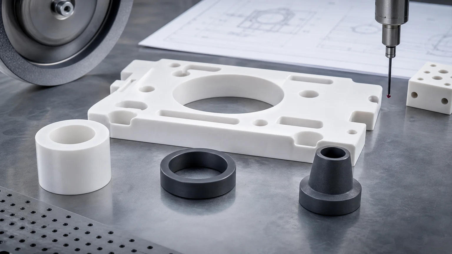
Ceramic CNC machining design starts before the first toolpath. Advanced ceramic parts need geometry that can be supported, ground, lapped, cleaned, inspected, and protected without turning edge chips, hidden cracks, or quote ambiguity into the real acceptance criteria.
Ceramic CNC machining is often selected when a component needs electrical insulation, wear resistance, thermal stability, corrosion resistance, vacuum compatibility, or dimensional stability beyond what metals and polymers can provide. The same material advantages also change the design rules. Alumina, zirconia, silicon nitride, silicon carbide, aluminum nitride, MACOR, and boron nitride do not respond to cutting force, sharp corners, thin walls, and internal features the way aluminum or stainless steel parts do.
For engineers and sourcing teams, the goal is not to make every ceramic drawing look conservative. The goal is to identify which features must be precise, which features can be relaxed, which process route is realistic, and which inspection method can prove acceptance.
This guide focuses on design rules that make advanced ceramic parts more practical to review for machining and RFQ. Final feasibility, price, and lead time still depend on material grade, blank state, drawing revision, tolerance map, surface finish, quantity, and inspection requirements.
Rule 1: Design Around The Ceramic State
The first design question is not only material name. It is material state.
Advanced ceramic parts may be shaped before sintering, machined after firing, ground with diamond tools, lapped on functional faces, or produced from a machinable ceramic blank. Each route affects geometry, tolerance, cost, and risk.
| Ceramic state or route | Typical design implication | RFQ note |
|---|---|---|
| Green machining before sinter | Useful for some shapes before final hardness, but shrinkage must be controlled | Confirm allowance, shrinkage strategy, and features needing final finish |
| Fired ceramic CNC machining | Suitable for accessible features, usually slower than metal cutting | Define critical faces and avoid unnecessary tight requirements |
| Diamond grinding | Common for tight faces, bores, flats, OD/ID relationships, and datum features | Apply it where function needs precision |
| Lapping or polishing | Used for seal faces, flatness, low Ra, and controlled contact surfaces | Specify which face or band needs this finish |
| MACOR or machinable ceramic | Useful for prototypes, fixtures, and fast-turnaround insulating parts | Validate whether the grade fits the final environment |
| Sintered SiC, Si3N4, ZrO2, Al2O3 | High-performance materials often require abrasive finishing for demanding requirements | Review feature access, edge quality, and inspection method |
Designs become easier to quote when the drawing separates near-net geometry from final functional geometry. If a surface can remain as-sintered or standard-ground, say so. If a bore, face, or datum must be finished after sintering, identify it clearly.
Rule 2: Put Tight Tolerance Only Where It Works
Tight tolerance is not bad. Unfocused tight tolerance is expensive and risky.
Ceramic CNC machining becomes more predictable when the drawing separates:
- Datum faces that control the part in the assembly.
- Functional bores, pins, shoulders, and alignment features.
- Seal lands, sliding faces, and wear interfaces.
- Thermal-interface or electrical-contact surfaces.
- Flow-control holes, nozzles, or gas distribution features.
- Non-critical outside profiles and clearance geometry.
For example, a ceramic spacer may need parallel end faces and controlled thickness, but the outside profile may not need the same tolerance. A zirconia plunger may need roundness, OD finish, and end-face condition, while a rear relief can be less strict. A silicon carbide seal ring may need lapped flatness on one face, but not a low Ra callout on every surface.
Before sending an RFQ, mark the features that actually create function. The supplier can then review whether CNC machining, diamond grinding, lapping, or a combined route is appropriate. See the related ceramic tolerance capability map for a feature-by-feature way to think about tolerance ranges.
Rule 3: Replace Sharp Internal Corners With Radii
Sharp internal corners are common in metal drawings. They are often a poor fit for advanced ceramics.
Ceramics are strong in compression, but sharp notches and abrupt transitions can concentrate tensile stress. The same corners can also chip during machining, grinding, handling, cleaning, and assembly. Internal radii reduce stress concentration, improve tool access, and make edge quality easier to control.
Use radii for:
- Pocket corners.
- Slot ends.
- Step transitions.
- Relief features near thin walls.
- Bore-to-face transitions when the design allows.
- Internal channels and flow paths that do not require a sharp corner.
If a sharp corner is truly functional, call it out as a review item instead of assuming it is a normal CNC feature. The supplier may need to propose a relief, split feature, secondary operation, or inspection limit.
Rule 4: Define Edge Breaks Instead Of Leaving Edge Quality Implied
Edge condition is a real design feature in ceramic CNC machining. Unspecified edges create uncertainty because the buyer may expect a crisp profile while the supplier needs to prevent chips.
Define:
- Which edges are functional and must stay controlled.
- Which edges may receive a small chamfer or radius.
- Whether chips are allowed, and on which faces they are unacceptable.
- Whether edge break affects sealing, insulation, flow, or fit.
- Which inspection method will evaluate edge quality.
This matters for alumina insulators, zirconia wear pins, silicon nitride guide parts, SiC seal faces, AlN thermal plates, and micro-hole components. A small edge defect may be cosmetic on one face and critical on another.
For broader DFM guidance, the existing ceramic DFM design rules page covers go/no-go features such as sharpness, thin walls, slots, and inspection access. This article extends that logic specifically into ceramic CNC machining and RFQ review.
Rule 5: Treat Holes As Machining And Inspection Features
Holes in ceramic parts are not just diameter notes. They are edge, depth, access, taper, breakout, and inspection features.
A ceramic hole should be reviewed by:
- Diameter and tolerance.
- Material and fired state.
- Through-hole or blind-hole geometry.
- Depth-to-diameter ratio.
- Distance to nearby edges, slots, or walls.
- Entry and exit edge condition.
- True position and datum strategy.
- Taper allowance, if flow or fit depends on it.
- Cleaning and particle-control expectation.
- Optical, pin, CMM, air-flow, or section-based inspection need.
Micro-holes, gas distribution plates, vacuum features, nozzle bores, and high-voltage insulation holes need especially clear drawings. When hole count increases, quote risk can come from yield, cleaning, burr-like edge defects, measurement time, and positional evidence rather than the nominal diameter alone.
For small-hole RFQs, the ceramic micro-hole machining guide gives a more focused checklist.
Rule 6: Keep Thin Walls Supported And Functional
Thin ceramic walls can be necessary for insulation, flow control, weight reduction, thermal response, or space constraints. They also increase breakage risk.
A thin-wall feature should have a clear reason. If it is only the result of copying a metal design, it may be worth redesigning before RFQ.
Review these points:
- Minimum wall thickness and wall height.
- Adjacent slot or pocket radius.
- Whether the wall is supported during grinding or inspection.
- Whether the wall sees bending, clamping, vibration, thermal shock, or assembly force.
- Which faces need final finish.
- How the part will be packaged and handled.
Ceramic thin walls can be practical when the material, route, and support conditions are reviewed together. Unsupported long walls, sharp slot roots, deep pockets beside thin ribs, and tight tolerance on both sides of a fragile wall deserve focused review before quoting.
Rule 7: Make Slots, Pockets, And Grooves Tool-Friendly
Slots and pockets are common in ceramic fixtures, electrical parts, wafer-adjacent components, and wear guides. They are also common sources of quote variance.
Design rules for ceramic CNC machining include:
- Use radiused slot ends instead of square ends when possible.
- Avoid narrow, deep grooves unless the feature is clearly functional.
- Provide tool access and exit paths.
- Avoid placing tight tolerances on every pocket wall.
- Define bottom finish only when it matters.
- Avoid thin unsupported ribs between neighboring pockets.
- Separate rough clearance pockets from finished datum or contact areas.
If the design needs a slot for flow, alignment, insulation spacing, or mechanical clearance, describe that function. The supplier can then review whether width, depth, radius, and edge quality are reasonable for the chosen material and route.
Rule 8: Build Datums Around Real Contact Surfaces
Datums should reflect how the ceramic part is machined, inspected, and used. A datum placed on an inaccessible, rough, or non-functional surface creates confusion.
Good ceramic datum strategy usually uses:
- Finished faces that can be held and measured.
- Bores or shoulders that control real assembly alignment.
- Flat areas with enough size for inspection contact.
- Datum targets when only limited pads are functional.
- A sequence that matches how the part sits in the assembly.
Avoid using decorative or clearance surfaces as primary datums. Also avoid stacking tight position tolerances from surfaces that will not be finished. If a datum face must be lapped, ground, or protected from chips, say so.
A clear datum plan lets the supplier evaluate fixtures, process route, CMM access, and whether the tolerance scheme can be accepted with practical measurement evidence.
Rule 9: Specify Surface Finish By Function, Not Habit
Surface finish is one of the strongest cost drivers in precision ceramic parts. A blanket low-Ra requirement can move a part from standard machining into grinding, lapping, polishing, or extended inspection without improving the assembly.
Specify low Ra only where it supports:
- Sealing.
- Sliding or wear.
- Vacuum contact.
- Heat transfer.
- Electrical interface.
- Optical, sensor, or metrology performance.
- Cleanliness or particle-control requirements.
Other faces may use standard ground, as-fired, or non-critical finish depending on the application. When surface integrity matters, define both the face and the acceptance method. A seal face, for example, may need flatness, Ra, edge quality, and packaging control. A cosmetic finish note alone is not enough.
The surface finish and subsurface damage guide explains how surface requirements affect cost and acceptance risk.
Rule 10: Design For Measurement Before Sending The RFQ
A ceramic part is not quote-ready just because the CAD model is complete. It must also be measurable.
Check whether the supplier can access:
- Datum faces.
- Internal bores.
- Hole arrays.
- Thin-wall thickness.
- Slot width and depth.
- Flatness and parallelism faces.
- Surface finish zones.
- Edge chip criteria.
- Critical concentricity or runout relationships.
For small holes, optical methods may be more useful than pin gauges. For flatness, the contact area and setup matter. For lapped faces, Ra and flatness may need separate acceptance methods. For internal channels, destructive sectioning or CT may be considered only when the project justifies it.
Inspection should not be added after the quote as an afterthought. It should be part of the RFQ because it affects route, cost, schedule, and acceptance evidence.
Rule 11: Match Material Choice To Feature Risk
Advanced ceramics are not interchangeable.
Alumina is widely used for electrical insulation, wear, vacuum, and general industrial components, but purity, density, and finish requirements still matter. Zirconia can be useful for tough wear parts and precision mechanisms, but temperature and environment must be reviewed. Silicon nitride often fits structural and wear applications where strength and thermal shock resistance matter. Silicon carbide can support harsh chemical, wear, seal, and semiconductor-adjacent environments, but it can also increase finishing difficulty. Aluminum nitride is selected for thermal management and insulation, where flatness, cleanliness, and surface condition can dominate the RFQ. MACOR and boron nitride can be practical for certain machinable, insulating, prototype, or high-temperature roles, but they are not generic substitutes for fired structural ceramics.
Feature risk changes by material. A radius, bore, thin wall, slot, or lapped surface that is practical in one grade may be more expensive or less reliable in another. Send the operating environment with the drawing so material choice and design rules can be reviewed together.
The ceramic material selection guide can help align material choice with machining and application risk.
Rule 12: Use The RFQ To Expose Design Assumptions
A good ceramic CNC machining RFQ does more than ask for price. It gives the supplier enough information to challenge risky assumptions before manufacturing starts.
Include:
- 3D CAD and controlled 2D drawing.
- Material grade, purity, or acceptable alternatives.
- Blank state or sourcing requirement.
- Functional surfaces and non-critical surfaces.
- Critical tolerances and GD&T.
- Surface finish by face or zone.
- Edge break and chip criteria.
- Hole count, hole depth, and hole inspection requirements.
- Quantity, prototype or production intent, and revision status.
- Cleaning, packaging, and documentation expectations.
- Application environment: temperature, load, wear, voltage, vacuum, media, thermal cycling, or cleanliness.
If you are not sure which tolerance is realistic, mark the functional need instead of forcing a number across the whole drawing. The supplier can review the feature and propose a route or adjustment.
Use the custom ceramic CNC machining RFQ checklist to prepare the drawing package before requesting a formal quote.
Practical Design Checklist
Before releasing an advanced ceramic part for CNC machining review, ask:
| Design question | Why it matters |
|---|---|
| Which surfaces create function? | Prevents tight tolerance everywhere |
| Which faces need grinding, lapping, or polishing? | Controls cost and process route |
| Are internal corners radiused? | Reduces stress concentration and chip risk |
| Are edge breaks and chip criteria defined? | Prevents acceptance disputes |
| Are holes reviewed for depth, position, edge, and access? | Reveals machining and inspection difficulty |
| Are thin walls supported and necessary? | Reduces fracture risk |
| Are datums measurable and functional? | Makes GD&T practical |
| Is surface finish specified by face? | Avoids unnecessary finishing cost |
| Is inspection method clear? | Makes acceptance auditable |
| Is the material matched to the environment? | Prevents false assumptions from catalog data |
Takeaway
Ceramic CNC machining design rules are not a list of restrictions. They are a way to make advanced ceramic parts more manufacturable, inspectable, and quote-ready.
The strongest drawings separate functional precision from non-critical geometry, use radii and edge breaks deliberately, define holes and thin walls as risk features, place datums on measurable surfaces, specify finish by function, and send enough RFQ context for review. That approach helps the supplier choose the right route before price, lead time, or feasibility are confirmed.
- Ceramic CNC machining
- Design rules
- Advanced ceramics
- DFM
- RFQ checklist