Published · Updated · CERAMIC CNC Engineering · Engineering Guide · 7 min read
Ceramic Wafer End Effectors: Material, Geometry, and RFQ
Choose and specify ceramic wafer end effectors by contact mode, material, fork geometry, robot interface, vacuum features, edge quality, and inspection.
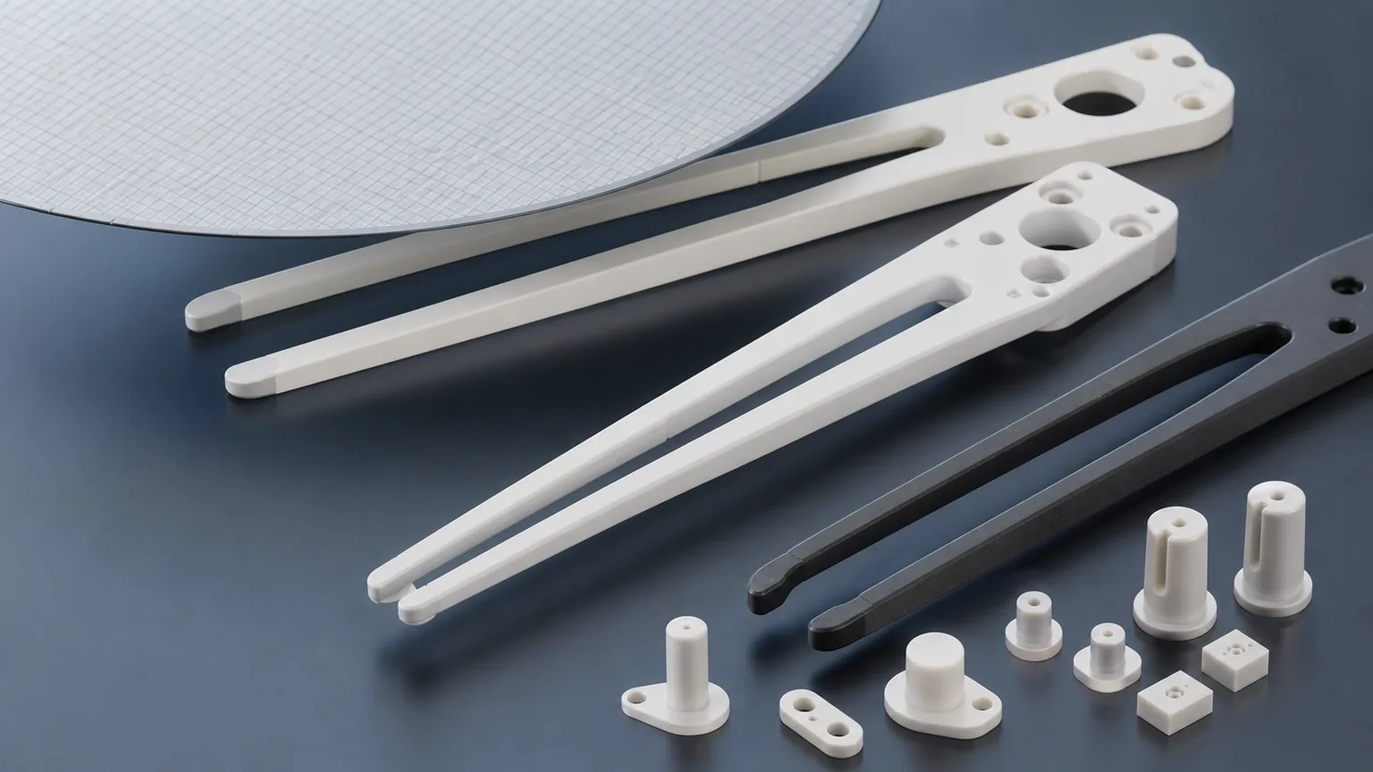
Choose a ceramic wafer end effector from the handling task outward: define the wafer, contact mode, speed, environment, robot interface, and acceptance method first. Then select a ceramic grade and machining route. Starting with a material name can lock the design into the wrong stiffness, weight, edge, thermal, or qualification tradeoff.
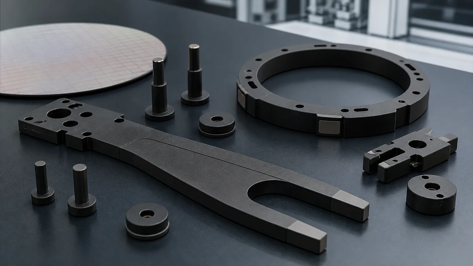
This guide serves engineers comparing materials and geometries for fork blades, paddles, edge grippers, vacuum picks, support fingers, and hybrid robot interfaces. If the design is already locked to silicon carbide, use the dedicated SiC wafer-handling parts guide for contact-zone, grade, cleaning, and inspection details.
Start With the Handling Method
| End-effector type | Handling method | Design question that comes first |
|---|---|---|
| Fork blade | Supports the wafer at two or more underside contacts | Where are the contact pads and how does the fork resist deflection? |
| Paddle | Supports a broader area | Which face controls flatness and how is trapped contamination avoided? |
| Edge gripper | Contacts the wafer or carrier at its edge | What radius, force, and chip criterion protect the contact? |
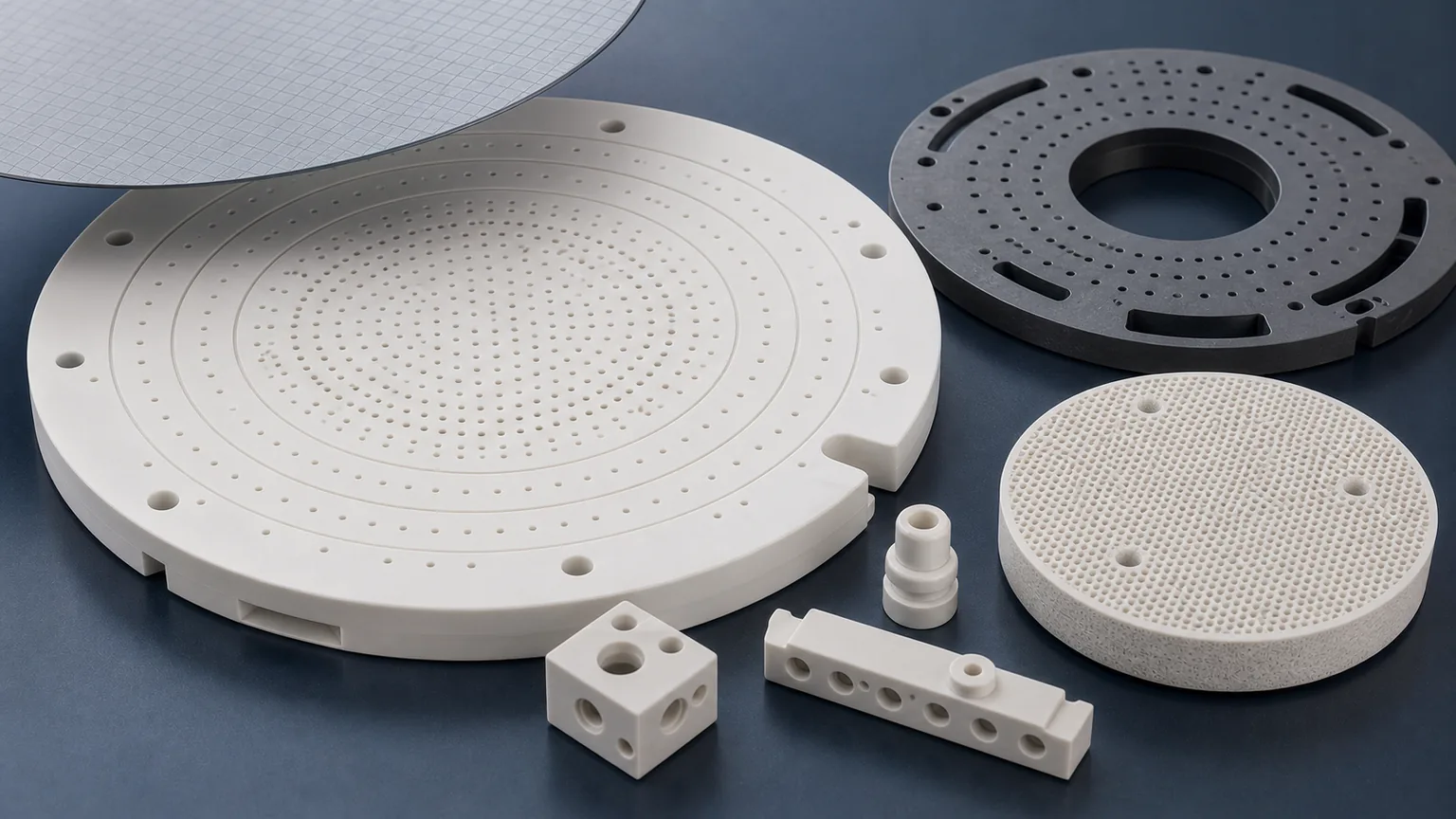
| Vacuum pick | Uses holes, grooves, or a suction land | What vacuum path, leakage boundary, surface condition, and cleaning method apply? |
| Support fingers or pins | Provides local lift or temporary support | Are height, tip geometry, and matched-set control required? |
| Hybrid ceramic/metal assembly | Keeps ceramic at the contact zone and metal at the robot interface | How are load, thermal expansion, fasteners, bonding, and datums managed? |
Also state whether the part handles a bare wafer, glass substrate, ceramic substrate, carrier, ring, or another fragile workpiece. The same fork outline can require a different surface and edge strategy for each contact.
Material Selection for Ceramic End Effectors
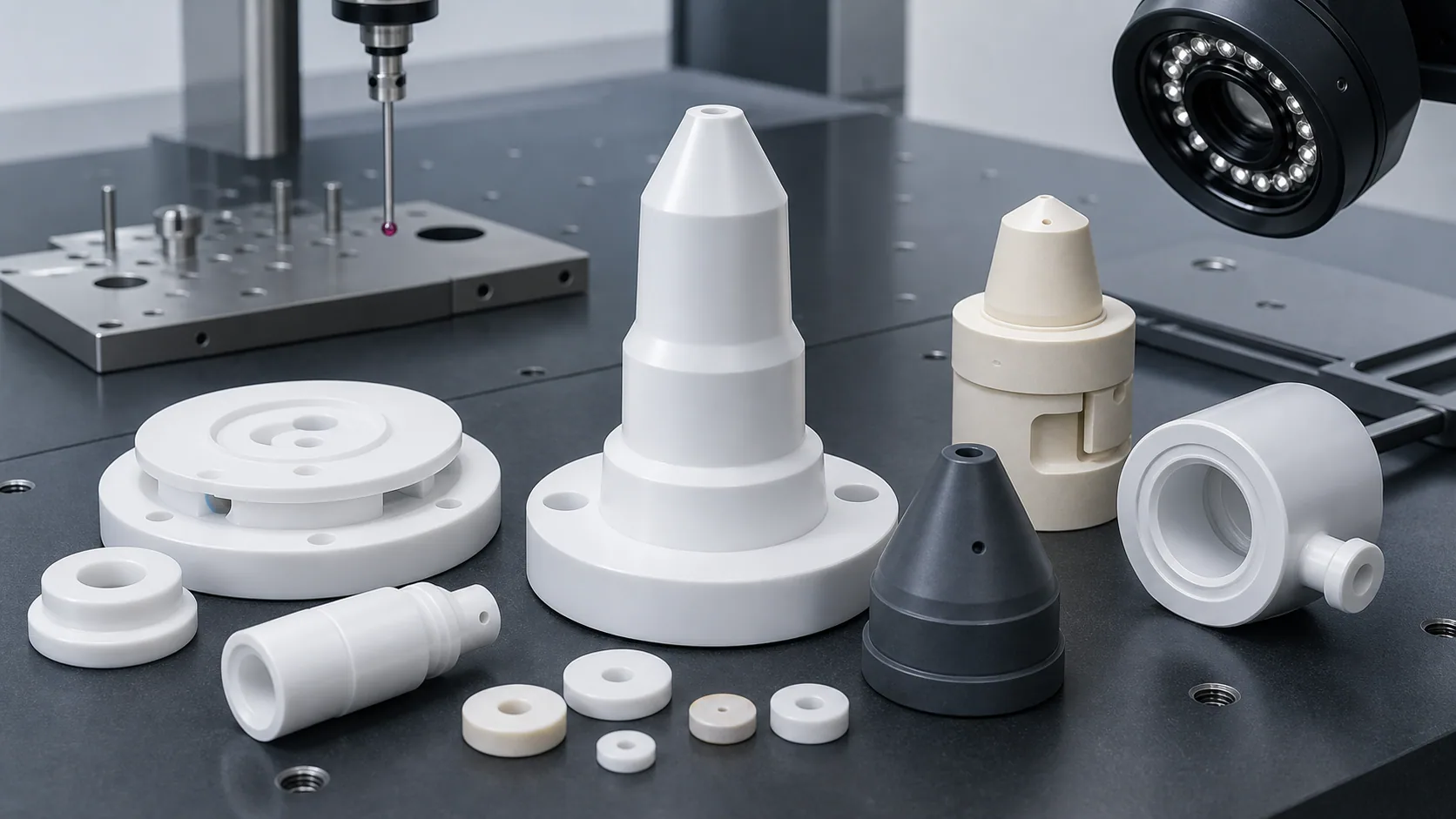
No ceramic is the default for every handling system. Compare the exact grade and qualification status, not only the material family.
| Material family | Why it may be reviewed | Questions before selection |
|---|---|---|
| Silicon carbide (SiC) | Stiff, wear-resistant, thermally stable, and used in semiconductor handling hardware | Is the exact grade qualified? Can the thin geometry and contact finish be produced and inspected? |
| Alumina (Al2O3) | Electrical insulation, broad grade availability, and practical custom components | Which purity, thickness, contact surfaces, and edge criteria are required? |
| Silicon nitride (Si3N4) | Structural strength, low density, wear, and thermal-shock resistance in selected mechanisms | What load, shock, sliding contact, and grade data govern the choice? |
| Zirconia (ZrO2) | Tougher local contact pads, pins, or gripper elements | Are temperature, wear pair, stiffness, and mass suitable for the system? |
| Aluminum nitride (AlN) | Electrical isolation with thermal transfer for heater-adjacent interfaces | Are thermal faces, moisture handling, thin sections, and edge protection controlled? |
| Macor or machinable ceramic | Rapid prototypes, laboratory automation, and geometry learning | Do service temperature, strength, thermal shock, particles, and production qualification permit it? |
Material properties alone do not decide the end effector. A lower-density material may reduce moving inertia, but the required arm thickness can change. A high-stiffness material may help deflection, but a narrow slot or sharp transition can reduce manufacturing yield. The ceramic material selection guide provides the broader comparison.
Contact Geometry Is the Functional Core
Mark the contact surfaces explicitly on the drawing. For each contact, state:
- Wafer or substrate size and orientation.
- Underside, edge, vacuum, or temporary-lift contact.
- Contact-pad location, size, radius, and spacing.
- Allowed marks and contamination limits.
- Flatness, profile, or height relationship.
- Surface finish on the named contact area.
- Edge break, radius, chamfer, and allowable chip size.
- Free-state, supported, or assembled measurement condition.
Do not apply a low-Ra requirement to the entire blade unless the full blade is functional. Localizing the requirement makes the quotation clearer and directs lapping and inspection to the interface that matters.
Fork Geometry and Deflection Risk
Thin ceramic arms need a load-path review as well as a machining review. Include the wafer mass, acceleration, arm length, support pattern, and any emergency or maintenance load the design owner considers relevant. The ceramic machining supplier can review manufacturability, but the equipment owner remains responsible for system-level stress and motion validation.
Features that commonly need revision include:
- Long unsupported arms with narrow transitions.
- Sharp internal slot corners.
- Small hole-to-edge distance near the mounting body.
- Counterbores or pockets that leave a thin back wall.
- Contact pads too close to a fragile tip.
- Abrupt thickness changes without a transition radius.
- Blanket tight profile on noncontact outside edges.
Use the ceramic CNC machining design rules before releasing a metal-derived fork design for ceramic quotation.
Robot Mounting Interface
Handling accuracy is lost if the ceramic contact zone cannot be related to the robot interface. Define:
- Primary mounting face and finished datum pads.
- Bore, dowel, slot, or counterbore position.
- Relationship from mounting datums to wafer-contact pads.
- Parallelism or profile between the contact plane and interface plane.
- Clamping direction, fastener method, torque or preload context.
- Bonded, inserted, isolated, or direct-clamp assembly route.
- Replacement alignment or calibration procedure where relevant.
Avoid a tolerance scheme that references an unground as-fired face when a finished, inspectable datum is available. The ceramic tolerance capability map explains how datum access and measurement method influence feasibility.
Vacuum Picks and Suction Features
Vacuum end effectors introduce a separate fluid path. Define hole diameter, depth, taper, pitch, entry and exit condition, groove geometry, port connection, suction land, and cleaning method. Decide whether acceptance is dimensional, functional, or both.
Questions that should be answered before quotation:
- Is the hold created by discrete holes, a groove network, a porous insert, or a separate pad?
- Which face is lapped before or after holes are made?
- Is a flow, leakage, or holding test required?
- How will small passages be checked for blockage and residue?
- Can the vacuum land be measured without distorting a thin blade?
Use the vacuum-chuck flatness guide for larger suction surfaces and the micro-hole guide when small passages dominate the route.
Edge Quality, Cleaning, and Packaging
For wafer handling, edge control is functional rather than cosmetic. Divide the drawing into:
- Wafer-facing tips and pad edges.
- Fork-slot and vacuum-feature edges.
- Mounting holes and assembly edges.
- Nonfunctional exterior edges.
Assign radius, chamfer, chip limit, and visual method only where needed. Then specify cleaning and packaging that preserve the accepted condition. Fork tips, contact pads, and matched support fingers should not touch each other during shipment.
Inspection Plan for a Ceramic End Effector
| Functional requirement | Evidence to agree |
|---|---|
| Contact-pad height or flatness | Flatness map, CMM, optical method, or fixture-based report |
| Contact plane to mounting datum | CMM, profile, or assembly gauge |
| Fork arm profile and slot width | Optical scan, CMM, comparator, or agreed key dimensions |
| Edge condition | Zone-based visual inspection with defined magnification and chip criterion |
| Contact-surface finish | Ra or other agreed surface result on the named pads |
| Vacuum holes or grooves | Optical check, flow test, leakage test, or blockage inspection |
| Matched fingers or pins | Set-height report, identification, and protected set packaging |
The inspection method should be agreed before the tolerance is priced. A nominal callout that cannot be accessed or repeated by the chosen method creates avoidable disagreement.
RFQ Checklist
Provide:
- Controlled drawing and STEP or native CAD.
- End-effector type and handling sequence.
- Wafer, substrate, or carrier size, mass, orientation, and contact mode.
- Candidate material, approved grade list, or operating requirements for material review.
- Robot or fixture interface, datums, fastener or bonding method, and mating parts.
- Contact pads, particle-sensitive edges, vacuum path, and functional faces marked by zone.
- Critical dimensions, GD&T, finish, edge, and inspection method.
- Cleaning, packaging, certificate, and traceability expectations.
- Prototype and production quantity, target timing, and qualification boundary.
The custom ceramic machining RFQ checklist can be used to normalize supplier quotes. Submit a ready drawing package through the technical RFQ page.
Common Questions
Which ceramic is best for a wafer end effector? There is no universal best material. SiC, alumina, silicon nitride, zirconia, AlN, and machinable ceramics fit different contact, stiffness, thermal, electrical, qualification, cost, and prototype needs.
Can a metal end-effector drawing be converted directly to ceramic? Usually it needs review. Sharp corners, thin webs, small edge distances, fastener loads, and broad tight tolerances may not transfer safely or economically to a brittle ceramic.
Is SiC always preferred for wafer handling? No. SiC is established in demanding wafer-handling hardware, but grade qualification, electrical behavior, geometry, cost, blank route, and the actual tool environment decide whether it is appropriate.
What should be inspected first? Prioritize the relationship among wafer-contact surfaces, robot mounting datums, particle-sensitive edges, and any vacuum features. These interfaces usually matter more than cosmetic outside dimensions.
Technical References
- CoorsTek: ceramic components for wafer processing and handling
- Precision Ceramics: technical ceramic material property comparison
RFQ note: Final material, geometry, tolerance, price, lead time, cleaning, packaging, and inspection scope depend on drawing review, grade, blank state, quantity, process route, robot interface, and agreed acceptance criteria.
- Ceramic end effectors
- Wafer handling
- Semiconductor automation
- Material selection
- Robot interface
- Ceramic DFM
- Inspection
- RFQ checklist