Published · Updated · CERAMIC CNC Engineering · Engineering Guide · 12 min read
Ceramic Locating Pins and Fixture Plates: Design and RFQ
Specify ceramic locating pins, precision bores, datum faces, fits, edge criteria, inspection evidence, and protected packaging for repeatable manufacturing fixtures.
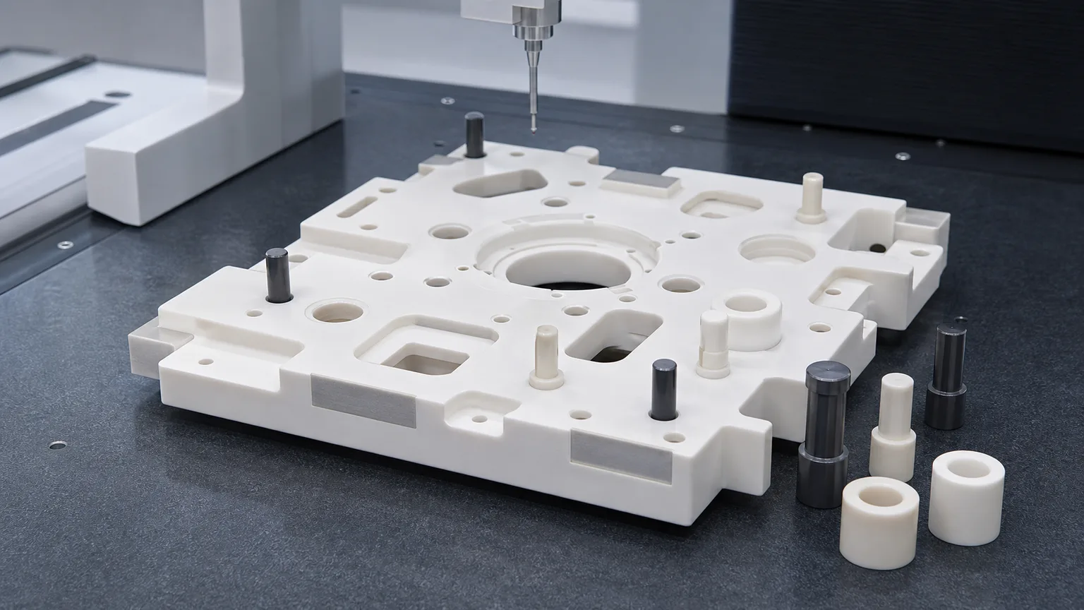
A quote-ready ceramic fixture drawing defines how the plate locates, how each pin is retained, which surfaces establish the coordinate system, and what inspection proves the relationship. A material name and a STEP model are not enough.
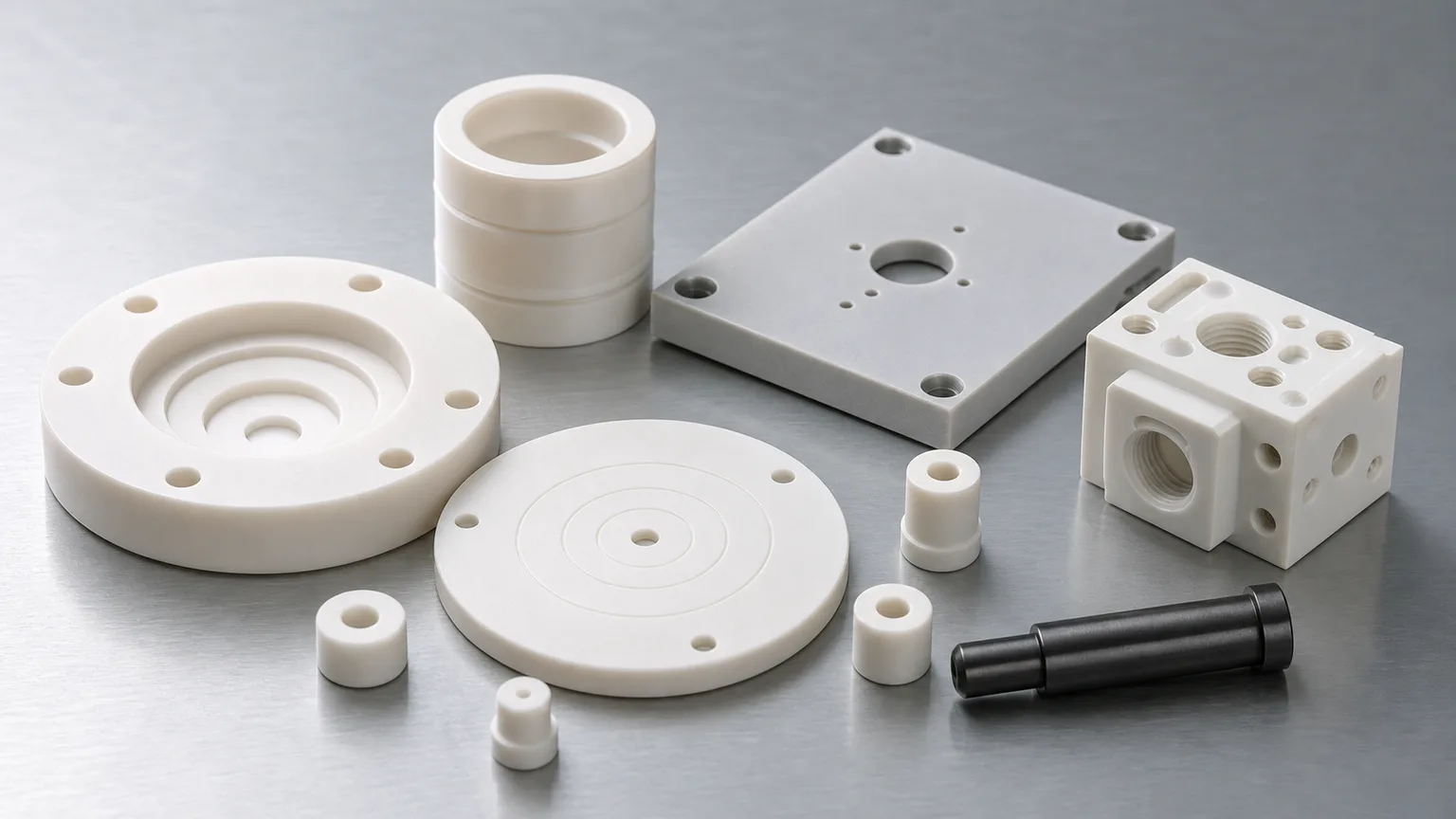
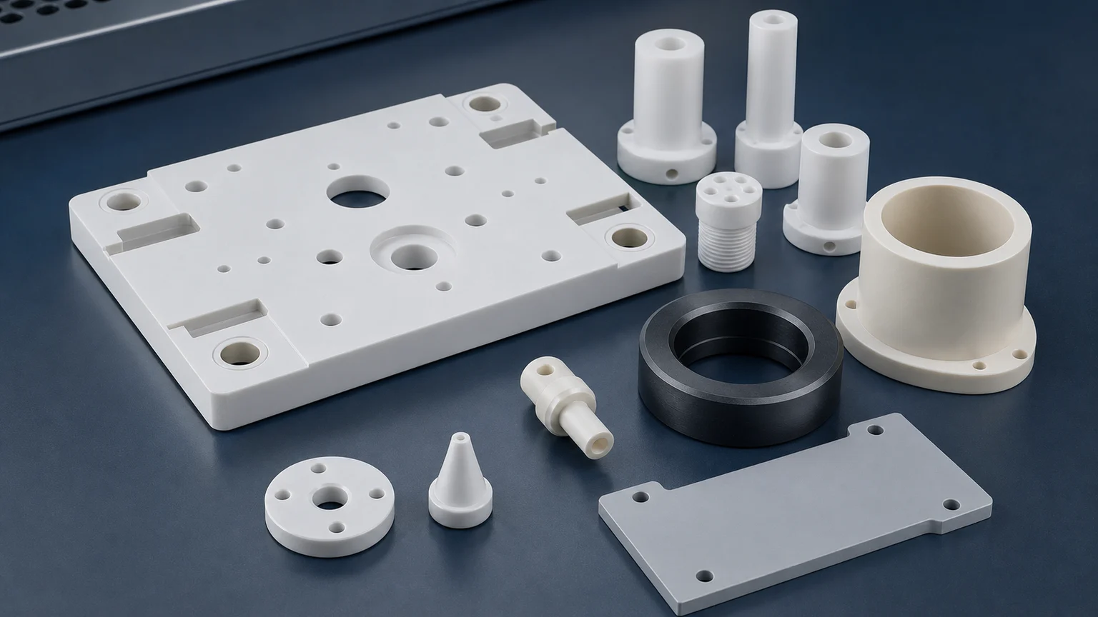
Ceramic locating pins and fixture plates are used when a production or inspection station needs some combination of wear resistance, electrical insulation, corrosion resistance, clean handling, or stable reference geometry. The buyer’s primary task is not to request the tightest possible tolerance. It is to separate the features that locate the workpiece from the features that only fasten, clear, or protect it.
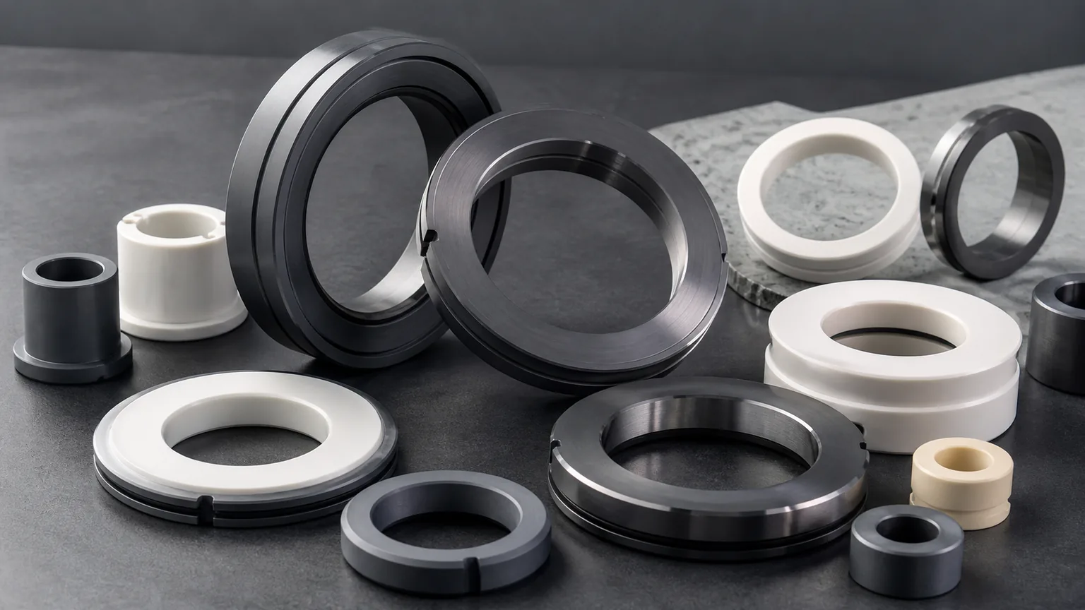
This guide covers custom fixture plates, locating pins, guide pins, datum pads, bushings, nests, and reference blocks for automation, metrology, semiconductor inspection, sensor assembly, and clean production equipment. It does not claim that every ceramic, pin fit, or tolerance is suitable. Final feasibility depends on the material grade, fired blank, geometry, support condition, quantity, and agreed measurement method.
For the wider application path, see precision ceramic components for automation, vacuum, and instruments. For a complete file package, use the custom ceramic machining RFQ checklist.
Start With The Locating Function
A fixture may contain twenty holes but use only two of them to establish position. It may have a large ground face but locate the workpiece on three small pads. It may use one round pin and one relieved pin to prevent the workpiece from being over-constrained. Unless these functions appear on the drawing, the supplier cannot know which relationships deserve the most machining and inspection effort.
Divide the assembly into five feature classes before requesting a quote:
| Feature class | Typical examples | What the drawing should establish |
|---|---|---|
| Primary references | Datum face, three support pads, reference edge | Which features create datum A and how the plate is supported during inspection |
| Locating features | Round pin, relieved pin, precision bore, V-block, nest wall | Fit, contact direction, insertion depth, allowed clearance, and position from datums |
| Retention features | Screws, clamps, adhesive pockets, pin shoulders | Assembly method, preload or torque context, and whether the supplier installs the hardware |
| Clearance features | Oversize holes, relief pockets, cable or sensor passages | Minimum clearance and practical edge break without unnecessary precision |
| Protected interfaces | Lapped pads, pin tips, probe zones, clean contact surfaces | Surface finish, chip limits, cleaning, packaging, and incoming inspection |
The datum scheme should describe the installed function. Using an easy-to-measure face as a datum is not useful if the fixture locates from a different face in the machine.
Fixture Plate And Pin Requirements Are Different
The plate and the pins are usually controlled by different failure modes.
The fixture plate is commonly driven by:
- Datum-face flatness or the coplanarity of discrete support pads.
- Position of locating bores relative to the functional datums.
- Plate thickness, local pad height, and parallelism where stack height matters.
- Slot, pocket, and counterbore geometry around brittle webs and corners.
- Edge condition near workpiece contact, probes, sensors, or clean surfaces.
- Free-state, supported, or clamped inspection condition.
The locating pin is commonly driven by:
- Working diameter, roundness, straightness, and cylindricity.
- Runout between the working diameter, shoulder, and mounting diameter.
- Lead-in radius or chamfer and the allowable condition of the pin tip.
- Shoulder squareness and installed height.
- Sliding, static, repeated-insertion, or wear-contact duty.
- Retention method and the stress it places into the ceramic.
Treating the pin as a small turned metal part can create a poor ceramic design. Sharp shoulders, knife edges, abrupt diameter changes, and uncontrolled press fits concentrate stress where a brittle material is least forgiving.
Choose Material By Interface, Not By Color
The same fixture may use an alumina plate and zirconia or silicon nitride pins. That is often more sensible than forcing every component into one material.
| Material direction | Where it may fit | Review before locking the drawing |
|---|---|---|
| Alumina | Fixture plates, insulating nests, spacers, datum blocks, general guide bushings | Grade or purity, blank size, finished datum faces, chip-sensitive bores, cleaning |
| Zirconia | Compact locating pins, plungers, small wear contacts, smooth guide components | Temperature, working surface, pin diameter, roundness, counterface, impact and wear mode |
| Silicon nitride | Slender guide pins, rollers, shafts, thermally cycled or mechanically loaded references | Exact grade, load path, shoulder transition, finish, blank route, inspection access |
| Silicon carbide | Stiff reference structures, harsh-wear plates, selected clean or thermal fixture parts | Grade, blank availability, edge risk, finished pads, chemical environment, mounting stress |
| Macor | Prototype nests, adjustment fixtures, threaded laboratory hardware, geometry trials | Service limit, thread load, edge strength, production-material transition, cleaning |
Kyocera’s fine-ceramics catalog describes ceramics in reference jigs, measuring tools, and stages for optical measuring instruments, where dimensional accuracy and wear resistance support repeatable measurement. That is useful application evidence, but it is not a universal capability specification for another supplier or grade. The actual material callout should still be tied to the fixture environment and drawing. Kyocera fine ceramics catalog
If electrostatic behavior matters around electronic devices, do not assume ordinary zirconia is dissipative. Conductive or ESD-controlled grades are separate material systems and must be specified by grade and acceptance method. Kyocera’s ESD-protection zirconia overview illustrates why this is a material-property decision rather than a color or finish decision.
Define The Pin-To-Bore Interface
The phrase “ceramic pin in ceramic plate” leaves several critical decisions open.
| Interface | Questions to answer before quotation | Main ceramic risk |
|---|---|---|
| Customer-installed slip-fit pin | What clearance, insertion length, shoulder stop, and replaceability are required? | Entry-edge chips, binding from misalignment, ambiguous installed height |
| Supplier-installed retained pin | Is retention adhesive, clamp, thread, shoulder, or another approved method? | Assembly stress, cure or cleaning compatibility, uninspectable final interface |
| Press or interference fit | Why is interference necessary, and what stress analysis or validation supports it? | Tensile hoop stress can crack the plate or pin during installation or thermal cycling |
| Pin in metal body | What is the metal bore, thermal range, retention method, and contact length? | Thermal expansion mismatch, point loading, edge damage |
| Replaceable bushing and pin | Which element is sacrificial, and how is the replacement referenced? | Tolerance stack, mixed-lot fit, damage during service replacement |
For long bores or thin ceramic walls around the interface, use the thin-wall ceramic sleeve and bore concentricity guide. It explains why bore size alone does not control wall balance, straightness, and assembly behavior.
Do not assign a fit from a nominal CAD diameter. State the operating temperature, mating material, assembly sequence, required clearance or retention, and whether pins and plates are supplied as matched sets or interchangeable parts.
Use A Constraint Strategy That Can Be Inspected
A fixture that constrains the same direction more than once may bind when the plate, workpiece, or hole spacing changes within tolerance. A common design direction is to use one round locating feature to establish two in-plane directions and one relieved feature to establish the remaining direction. The exact strategy belongs to the customer’s mechanism design, but the RFQ should make the intended contact directions visible.
Useful drawing notes include:
- Identify the primary pin and the secondary relieved or directional locator.
- Mark the workpiece contact zones on each pin or nest wall.
- Distinguish removable pins from permanently retained pins.
- State whether a locating bore is measured before or after pin installation.
- Define installed height from the functional datum face.
- State whether plates and pins are interchangeable across lots or matched and serialized.
- Provide the mating part or its controlled dimensions when fit is critical.
The ceramic tolerance capability map can help separate drawing requirements from supplier guarantees. A tolerance is useful only when the feature, datum, support condition, and measurement method agree.
Put Precision Only On Functional Features
Blanket tolerances make fixture RFQs expensive without necessarily improving repeatability. Build the acceptance plan around the error budget.
| Functional requirement | Drawing control to discuss | Evidence to request |
|---|---|---|
| Stable support plane | Datum-face flatness or coplanarity of named pads | Flatness map, CMM, height sweep, or agreed supported measurement |
| Workpiece location | Bore or pin position from datum reference frame | CMM report or fixture-specific positional report |
| Repeatable insertion | Pin diameter, bore diameter, roundness, lead-in, clearance | Diameter and roundness results plus fit check when appropriate |
| Installed height | Pin shoulder location and perpendicularity to datum face | CMM or height measurement after agreed assembly stage |
| Sliding guidance | Working OD/ID, straightness, cylindricity, face-specific Ra | Roundness, profile, air/bore gauge, or roughness report as applicable |
| Particle-sensitive contact | Edge break and chip criteria by zone | Magnified visual inspection with an agreed acceptance reference |
| Repeat orders | Material grade, approved drawing revision, controlled inspection method | First-article record and lot-level report scope |
Do not request CMM data for a surface that the CMM cannot access reliably. Do not use a pin gauge to prove taper, straightness, or localized chipping that the gauge cannot reveal. Select evidence around the actual failure mode.
Design The Plate For Ceramic Machining
Fixture plates often combine pockets, slots, bores, pads, and mounting holes. The main DFM risks are thin webs, sharp internal corners, short edge distances, and over-specified faces.
Review these points before releasing the drawing:
- Add practical radii to pocket and slot ends.
- Keep precision bores away from fragile outside edges where possible.
- Avoid a thin wall between adjacent holes unless it is functionally necessary.
- Provide grinding access to critical datum pads and bore lead-ins.
- Define edge breaks by function instead of applying “break all sharp edges” without a size.
- Avoid making every exterior face a tight datum or cosmetic surface.
- State whether the plate is inspected free, on three points, on a surface plate, or in a customer fixture.
- Identify threaded inserts, metal clamps, or compliant mounting details when they reduce direct stress on ceramic.
The ceramic CNC design rules guide covers hole spacing, thin walls, internal radii, and edge control in more detail.
Surface Finish And Edge Quality Must Follow Function
Low roughness is not automatically better on every fixture surface. A lapped datum pad, sliding pin, workpiece-contact zone, clearance pocket, and exterior handling face have different jobs.
Apply finish requirements to named zones:
- Datum pads that control seating or height.
- Pin diameters and guide bores that create controlled motion or fit.
- Contact areas that touch a finished workpiece.
- Sealing, vacuum, or cleanable interfaces.
- Nonfunctional relief surfaces where a standard ground or machined finish is acceptable.
The surface finish and subsurface damage guide explains why Ra, lapping, polishing, edge chips, and grinding damage should not be collapsed into one generic “polished” note.
Inspection, Cleaning, And Packaging Form One Acceptance Chain
A fixture can pass dimensional inspection and still arrive unusable if pins contact each other, a datum pad is scratched, or residue remains in a bore. Plan preservation with the measurement method.
For first-article and repeat orders, discuss:
- The drawing revision and exact material grade.
- The inspection stage: separate components, assembled fixture, or both.
- The datum setup and support condition used for measurement.
- Key-dimension, CMM, roundness, flatness, Ra, and visual-edge report scope.
- Cleaning method and any customer-owned final clean.
- Individual separation for pins and bushings.
- Face protection for datum pads and lapped surfaces.
- Tray orientation, labels, matched-set identification, and lot traceability.
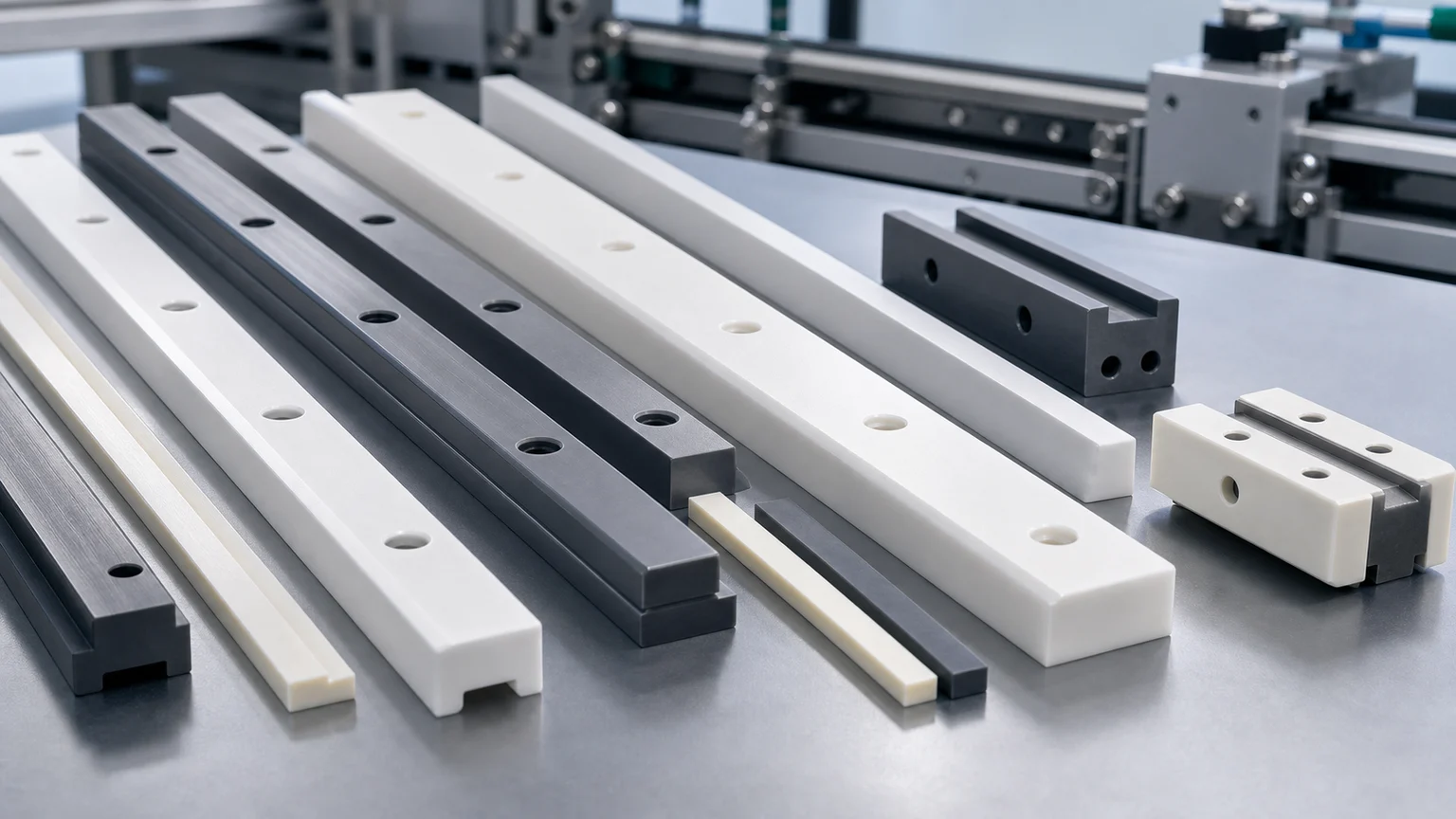
For clean or particle-sensitive stations, also review the cleanroom and high-purity ceramic component guide. For long wear interfaces adjacent to the fixture, see ceramic guide rails for production lines.
Where Ceramic Locating Hardware Fits
The same design logic appears across several application fields:
| Application | Typical ceramic hardware | Primary acceptance concern |
|---|---|---|
| Inspection and metrology | Reference plate, locating pin, nest, datum block, V-groove | Traceable location from stable datums and repeat-order consistency |
| Electronics and power-module assembly | Insulating nest, spacer, pin, support pad | Electrical isolation, component contact, installed height, ESD grade when required |
| Semiconductor and clean automation | Fixture plate, wafer-adjacent support, guide pin, protected nest | Particle-sensitive edges, cleaning, material traceability, protected packaging |
| Sensor assembly | Sleeve, alignment pin, holder, probe fixture | Axis location, bore alignment, assembly stress, contamination control |
| Optical and laser equipment | Mounting plate, spacer, alignment fixture, aperture support | Optical-axis references, low-distortion mounting, clean handling, customer optical qualification |
| Packaging and production machinery | Wear guide, locating block, replacement pin, bushing | Wear surface, interchangeability, mounting slots, field replacement |
For the optical application boundary, use the machined ceramic components for optical and laser equipment guide. For sensor interfaces, use the sensor and measurement-device ceramic guide.
Cost Drivers Buyers Can Control
The cost is usually driven by interactions among the plate, pin, inspection, and assembly requirements:
- Fired blank size, grade, and available stock allowance.
- Large finished datum faces or discrete matched-height pads.
- Bore position from finished datums.
- Long pin grinding, roundness, straightness, or multiple diameters in one pin.
- Tight pin-to-bore fits across interchangeable lots.
- Thin webs, deep pockets, narrow slots, and short edge distances.
- Supplier-side pin installation or matched-set assembly.
- Zone-specific chip criteria, microscopy, or full CMM reporting.
- Cleaning, individual protection, serialization, and repeat-order documentation.
Cost control means ranking features, not removing precision blindly. Keep tight requirements where the fixture establishes location or protects a sensitive interface. Relax clearance holes, nonfunctional pockets, hidden exterior faces, and cosmetic surfaces when the assembly permits.
RFQ Checklist For Locating Pins And Fixture Plates
Send the following for engineering review:
- 2D drawing and STEP or native CAD with revision.
- Fixture function and the part being located or inspected.
- Material grade for each plate, pin, bushing, and spacer, or the operating conditions needed for selection review.
- Primary, secondary, and tertiary datums.
- Locating, retention, clearance, and protected-contact features marked separately.
- Pin and bore fit, retention method, insertion depth, installed height, and replaceability.
- Mating materials, support condition, clamp or torque context, temperature, chemistry, voltage, wear, and cleanliness.
- Feature-specific flatness, position, roundness, straightness, runout, Ra, and edge criteria.
- Prototype and production quantity plus interchangeability or matched-set rules.
- Inspection, cleaning, packaging, traceability, and qualification requirements.
Send this package through the ceramic machining RFQ page. Price, lead time, achievable tolerance, assembly scope, and inspection plan should be confirmed only after the drawing, grade, blank, quantity, and acceptance method have been reviewed.
Frequently Asked Questions
Which ceramic is best for locating pins?
There is no universal best material. Zirconia may fit compact smooth wear contacts, silicon nitride may fit slender or mechanically loaded pins, and alumina may fit cost-sensitive insulating references. The decision depends on grade, load, temperature, wear mode, counterface, geometry, and required evidence.
Should a ceramic locating pin be press-fit?
Only after the interference, wall thickness, stress, thermal range, and installation method are reviewed. Adhesive retention, shoulders, clamps, replaceable bushings, or a metal holder may reduce tensile stress. A metal-style interference callout should not be copied without analysis.
Can a STEP file define the fixture well enough for quotation?
The STEP file defines geometry but usually not the functional datum system, fit, support condition, edge zones, material grade, surface finish, inspection, cleaning, or packaging. A controlled 2D drawing and application notes are normally needed.
Who validates final fixture repeatability?
The machining supplier can provide agreed dimensional, surface, material, cleaning, and packaging evidence. Final repeatability inside the customer’s machine, with the real workpiece, clamps, sensors, temperature, and process cycle, normally remains a customer qualification step unless a separate functional test is defined in the RFQ.
- Ceramic fixtures
- Locating pins
- Automation
- Metrology
- Alumina
- Zirconia
- Silicon nitride
- Inspection