Published · Updated · CERAMIC CNC Engineering · Engineering Guide · 16 min read
Silicon Nitride Ceramic Machining for Rollers and Wear Parts
How engineers should specify custom silicon nitride rollers, shafts, bearing-adjacent parts, sleeves, bushings, guides, and structural wear components.
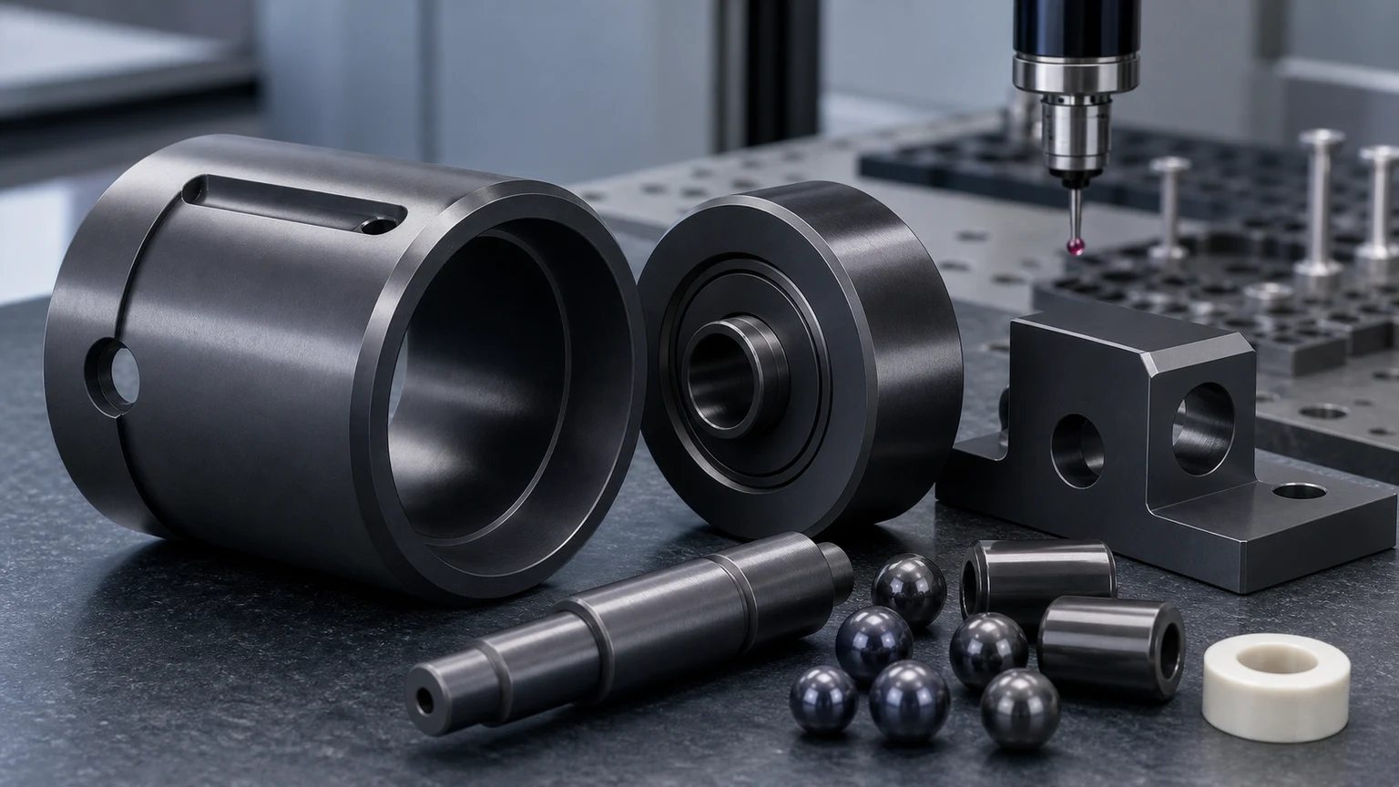
Silicon nitride ceramic machining is usually considered when a structural or wear component needs a combination of mechanical reliability, thermal shock resistance, low density, hardness, and stable performance under repeated contact. The material can be valuable, but the machined result depends on grade, blank condition, functional surfaces, tolerance scope, surface finish, edge quality, and inspection evidence.
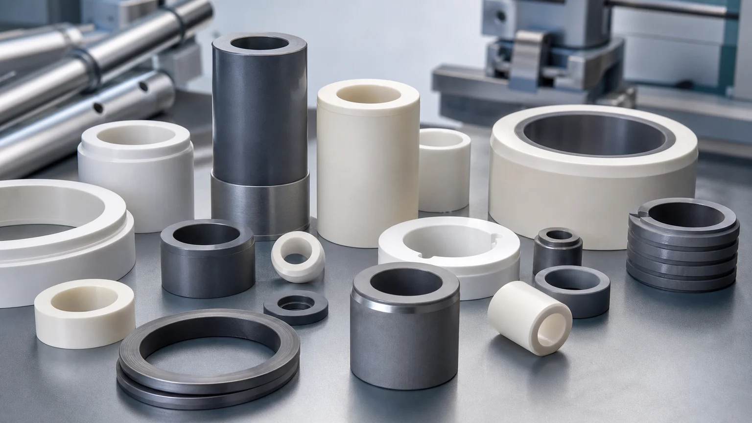
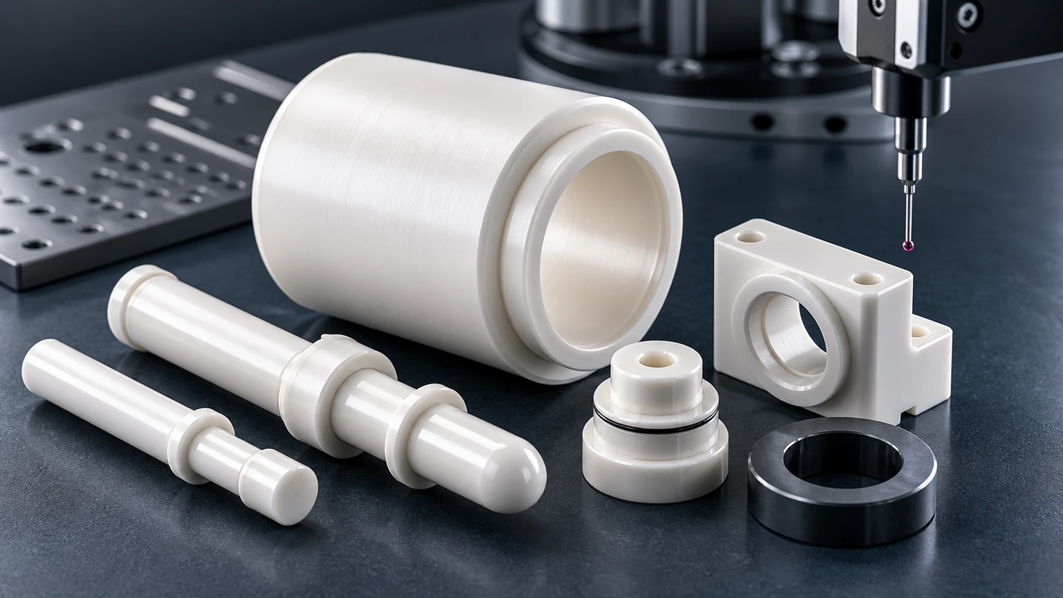
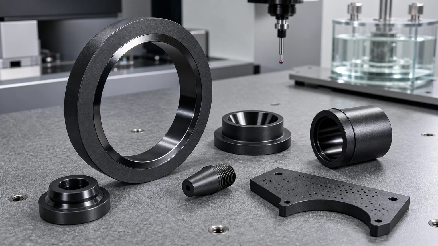
Silicon nitride ceramic parts are used in industrial automation, bearing-adjacent assemblies, high-speed motion systems, pump and valve hardware, welding and forming fixtures, thermal cycling equipment, metrology fixtures, laboratory instruments, and demanding wear mechanisms. Typical RFQs include silicon nitride rollers, shafts, sleeves, bushings, guide pins, locating components, wear pads, support blocks, bearing-related parts, and custom structural ceramic components.
This page covers the manufacturability and acceptance of custom machined ceramic components. It does not claim the supply of complete bearings, standard replacement bearings, certified bearing-grade balls, or a finished rolling-bearing life rating. Those products require a specialized material, rolling-element, raceway, assembly, lubrication, and endurance-qualification system beyond a dimensional ceramic machining report.
The practical sourcing question is not simply “Can silicon nitride be machined?”
The better question is:
Which Si3N4 grade, load path, running surface, tolerance map, edge condition, and inspection method are required for this part to survive in the assembly?
That question should be reviewed before feasibility, price, lead time, or production route is confirmed.
Why Silicon Nitride Is Used For Structural And Wear Components
Silicon nitride, often written as Si3N4, is chosen for applications where a ceramic part must handle mechanical contact, thermal cycling, sliding or rolling wear, and repeated assembly load more reliably than many conventional brittle ceramic options. Compared with general-purpose alumina, silicon nitride may offer better toughness, thermal shock behavior, and performance in high-speed or impact-sensitive wear situations.
This does not make silicon nitride a metal replacement in the simple sense. It still behaves as an advanced ceramic. It will not yield like steel, it can be damaged by sharp corners, and it can fail if the design concentrates load into a small unsupported edge. A successful silicon nitride component usually combines the right material grade with a geometry that respects ceramic machining and ceramic assembly behavior.
Silicon nitride is most useful when the design takes advantage of these strengths:
- Rollers and shafts that need hard, stable running surfaces.
- Sleeves and bushings that need wear resistance, low friction behavior, or insulation from metallic contact.
- Guide pins and locating components that must keep shape under repeated contact.
- Structural supports where low mass, heat resistance, and stiffness matter.
- Bearing-adjacent components where roundness, runout, finish, and fatigue behavior affect performance.
- Fixtures exposed to thermal cycling, weld heat, or abrasive contact.
The ceramic material selection guide gives a broader framework for comparing silicon nitride with alumina, zirconia, silicon carbide, aluminum nitride, MACOR, and boron nitride.
Silicon Nitride Compared With Alumina, Zirconia, And Silicon Carbide
Silicon nitride is often considered alongside alumina, zirconia, and silicon carbide because all four materials appear in precision industrial ceramic RFQs. The correct choice depends on function, not on a generic material ranking.
| Material | Where it is often considered | RFQ review focus |
|---|---|---|
| Alumina Al2O3 | Electrical insulation, general wear, fixtures, spacers | Purity, insulation path, edge quality, cost target, and functional surfaces |
| Zirconia ZrO2 | Tough precision pins, plungers, sleeves, and wear parts | Grade, edge risk, sliding fit, surface finish, and assembly stress |
| Silicon nitride Si3N4 | Structural wear parts, rollers, shafts, guides, bushings | Grade, load path, roundness, finish, thermal shock, and edge stability |
| Silicon carbide SiC | Chemical wear, seal faces, harsh media, high stiffness | Lapped surfaces, chemical environment, flatness, edge quality, and cost driver |
| Aluminum nitride AlN | Thermal management with electrical insulation | Flatness, thermal interface, cleaning, and assembly method |
| MACOR or machinable glass | Fast prototype, lab fixture, or moderate-service insulator | Service limit, prototype intent, final material transition, and feature access |
| Boron nitride BN | High-temperature insulation and release-contact parts | Grade, atmosphere, strength limit, and contact load |
For a general wear bushing, precision machined alumina ceramic may be more economical. For a compact plunger with high edge risk, zirconia ceramic machining may be reviewed first. For an aggressive fluid seal face, silicon carbide may be a stronger candidate. Silicon nitride becomes especially interesting when the part sees a combination of structural load, wear, thermal cycling, and geometry-driven reliability risk.
Common Silicon Nitride Machined Parts
Most silicon nitride machining projects become clearer when the part is described by its role in the machine.
| Part type | Common function | Critical review points |
|---|---|---|
| Rollers and wheels | Rolling contact, guide motion, high-speed handling | OD roundness, runout, bore fit, edge condition, surface finish, and speed |
| Shafts, pins, and plungers | Sliding, locating, actuation, or wear contact | OD size, cylindricity, end-face condition, chamfer, load path, and finish |
| Sleeves and bushings | Wear guidance, insulation, spacing, bore support | ID/OD relationship, wall thickness, concentricity, entry chamfer, and mating shaft |
| Guide blocks and locating parts | Repeatable positioning or abrasion-resistant mechanical guides | Datum faces, hole position, slot geometry, mounting load, and replaceable surfaces |
| Bearing-adjacent components | Bearing balls, rollers, races, spacers, or related hardware | Grade, surface integrity, roundness, fatigue risk, lubrication, and inspection plan |
| Structural ceramic supports | Heat-resistant supports, low-mass brackets, rigid insulators | Load direction, mounting interface, radii, flatness, and thermal cycling |
| Thermal cycling and weld fixtures | Heat exposure, contact with hot workpieces, abrasive fixtures | Shock exposure, contact pattern, edge break, replaceability, and cleaning method |
Two silicon nitride parts with similar outside dimensions may require very different machining routes. A simple spacer, a high-speed roller, a thin-wall sleeve, and a precision bearing-adjacent component should not be quoted as if they carry the same risk.
Grade And Blank Condition Must Be Defined
“Silicon nitride” is not a complete material specification. The grade, forming route, sintering route, density, additives, intended performance class, and supplier data can affect machining behavior and final use. Some projects require a customer-specified grade. Other projects start from the operating environment and then select a workable material option after review.
The RFQ should make clear whether the buyer needs:
- A specific silicon nitride grade from a drawing or approved vendor list.
- A general Si3N4 material suitable for a wear or structural function.
- A prototype grade for evaluation before production qualification.
- A production grade with lot traceability or inspection reporting.
- A replacement for an existing metal, polymer, alumina, zirconia, or silicon carbide part.
Blank state also matters. Silicon nitride can be shaped before final firing in some manufacturing routes, but many precision features in fired silicon nitride require diamond grinding, abrasive machining, lapping, or polishing. The final route depends on geometry, tolerance, finish, quantity, and how much material must be removed after sintering.
Machining Route: Why Fired Silicon Nitride Is Not Treated Like Metal
In metal CNC machining, a sharp cutter can remove material predictably across many feature types. Fired silicon nitride is different. It is hard, wear resistant, and brittle compared with metals, so precision features are usually produced with diamond abrasive processes rather than ordinary cutting tools.
A typical review may consider:
- Near-net blank geometry to reduce unnecessary grinding.
- Datum creation before critical features are finished.
- OD grinding for shafts, rollers, and cylindrical parts.
- ID grinding or honing-style finishing for precision bores.
- Surface grinding for flats, guide faces, and support surfaces.
- Lapping or polishing for selected running or sealing faces.
- Controlled edge break to reduce chipping risk without changing function.
- Inspection after critical grinding and final cleaning.
This route is one reason the ceramic CNC machining design rules are important. Features that are easy in aluminum or stainless steel may become high-cost or high-risk in fired silicon nitride if the drawing has sharp internal corners, deep narrow pockets, thin unsupported walls, or tight tolerances applied to every surface.
Silicon Nitride Rollers, Shafts, And Bearing-Adjacent Parts
Rollers, shafts, and bearing-adjacent silicon nitride components are often judged by geometry quality rather than by nominal size alone. A roller that meets outside diameter but fails roundness, runout, bore alignment, or edge quality can still create vibration, uneven wear, or assembly problems.
For these components, the drawing should define:
- OD tolerance and whether roundness or cylindricity is required.
- Bore tolerance, bore finish, and bore-to-OD concentricity.
- Runout relative to the functional axis.
- End-face squareness and parallelism if faces locate the assembly.
- Lead-in chamfers and edge break for assembly.
- Surface finish on rolling or sliding contact surfaces.
- Quantity and whether parts must be matched as a set.
The ceramic tolerance capability map is useful when deciding which dimensions need tight control and which dimensions can remain standard-ground or non-critical. Applying precision everywhere can increase cost without improving machine performance.
Separate A Custom Roller From A Bearing-Grade Rolling Element
The word “roller” can describe very different sourcing problems. A custom guide roller, transport roller, follower, insulating roller, or bearing-adjacent shaft may be quoted from a customer drawing with application-specific geometry and inspection. A rolling element for a qualified hybrid or all-ceramic bearing belongs to a more controlled product system.
ISO 26602:2017 covers preprocessed silicon nitride materials for rolling bearing balls and rollers. ISO 3290-2:2014 covers finished silicon nitride bearing balls. ISO 3643:2024 standardizes surface-defect terms and photographic examples for finished silicon nitride balls and rollers, but it does not set universal acceptance limits. The buyer and qualified bearing supply chain still have to define the defect limits appropriate to the application.
These standards create a useful RFQ boundary:
- If the requirement is a custom industrial roller or shaft, state the material grade, drawing features, contact surfaces, operating conditions, and dimensional evidence needed for that part.
- If the requirement is a bearing rolling element, state the applicable material and finished-product standards, size or grade class, defect criteria, lot controls, nondestructive evaluation, and bearing-manufacturer qualification route.
- If the requirement is a complete hybrid or all-ceramic bearing, procure and qualify the assembly as a bearing system rather than asking a ceramic machining quote to imply raceway, cage, lubrication, fatigue-life, and assembly performance.
Silicon nitride should not be described as automatically producing a longer-lived bearing. SKF’s discussion of its generalized bearing life model for hybrid bearings shows why operating conditions matter: rolling-contact pressure, load, lubrication, contamination, material fatigue, and raceway behavior interact. The engineering decision is conditional, not a generic material ranking.
For a custom rolling-contact part, add these inputs before quotation:
- Radial and axial load direction, load spectrum, shock, and expected failure mode.
- Rotational or linear speed, acceleration, starts and stops, and any short-stroke oscillation.
- Lubrication type, starvation risk, process contamination, moisture, vacuum, or corrosive exposure.
- Operating and transient temperature, thermal gradients, and mating-material expansion.
- Counterface or raceway material, hardness, geometry, finish, and replacement strategy.
- Electrical-current or insulation requirement, if it is one reason for considering a ceramic.
- Roundness, cylindricity, runout, diameter sorting or matched-set logic, and surface-defect limits.
- Material lot evidence, surface-integrity inspection, nondestructive evaluation, and customer endurance-test responsibility where the risk justifies them.
Dimensional conformance alone cannot prove rolling-contact fatigue life. The drawing and purchase specification should identify which acceptance evidence belongs to the ceramic component supplier and which qualification belongs to the bearing, machine, or system owner.
Silicon Nitride Sleeves, Bushings, And Guide Components
Sleeves and bushings look simple until the RFQ includes a tight bore, thin wall, high concentricity requirement, long length, and chip-sensitive entry edge. In silicon nitride, those details define the project.
For sleeve and bushing RFQs, the most important inputs are:
- Inner diameter, outer diameter, and length.
- Wall thickness and whether the wall is uniform around the part.
- ID-to-OD concentricity or total indicator runout.
- Bore straightness, roundness, and surface finish.
- Entry and exit chamfers.
- Shaft material, speed, load, lubrication, and assembly method.
- Whether press fit, slip fit, adhesive bonding, or mechanical retention is intended.
The thin-wall ceramic sleeve RFQ guide gives more detail on bore concentricity, wall stability, and drawing inputs for sleeve-style ceramic parts. Those same concerns apply strongly to silicon nitride when the sleeve is long, thin, or required to run against a precision shaft.
Guide blocks and locating components add another layer. Mounting holes, slots, pockets, and datum faces should be separated into functional and non-functional zones. A guide surface may need a controlled finish and flatness, while a clearance hole or non-contact face may not need the same cost level.
Silicon Nitride Structural Supports And Thermal Cycling Parts
Silicon nitride is also used for structural ceramic components where the part must resist wear, heat, thermal cycling, or repeated contact while keeping mass lower than many metallic alternatives. Examples include fixture supports, hot-work contact pads, welding-adjacent components, sensor supports, metrology fixtures, forming guides, and custom mechanical supports.
The design review should identify how load enters the part. Ceramics generally dislike point loading, sharp notches, unsupported tabs, and tensile stress concentrations. A support bracket or locating block should use generous radii where possible, broad contact surfaces, controlled mounting pressure, and practical chamfers.
Thermal cycling also changes the review. If the part repeatedly moves between hot and cool conditions, the RFQ should include:
- Maximum and minimum operating temperature.
- Heating and cooling rate if known.
- Contact material and contact pattern.
- Whether one surface is constrained while another surface expands.
- Cleaning method and chemical exposure.
- Shock, impact, or vibration conditions.
For electrical or high-power assemblies, silicon nitride may be reviewed alongside alumina and aluminum nitride. In some power electronics ceramic machining projects, thermal interface flatness, insulation path, and mechanical support all matter together, so the material choice should be reviewed against the full assembly instead of isolated property lists.
Design Rules That Reduce Silicon Nitride Machining Risk
Silicon nitride can support demanding designs, but the drawing should not copy metal-machining habits without review. Good ceramic design reduces avoidable cost and late-stage breakage risk.
Practical design rules include:
- Replace sharp internal corners with realistic radii.
- Avoid knife edges unless a controlled edge is truly functional.
- Keep holes away from thin edges and unsupported walls.
- Use chamfers or radii at assembly entries.
- Define the few surfaces that truly need tight tolerance or fine finish.
- Avoid deep narrow slots when a wider access path would work.
- Give grinding tools room to enter and exit.
- Avoid aggressive press fits unless the stress state has been reviewed.
- Mark datum faces clearly and align GD&T with the assembly function.
- Separate prototype geometry from production-qualified geometry if the design is still moving.
These rules are not only about manufacturability. They also protect the function of the final part. A brittle component with a technically achievable but poorly supported feature may pass inspection and still fail in service if the load path is wrong.
Cost Drivers In Silicon Nitride Ceramic Machining
Silicon nitride parts are often more cost-sensitive to geometry than to raw outside dimensions. A small part can be expensive if it requires multiple precision setups, fine lapping, deep ID grinding, or matched-set inspection.
Common cost drivers include:
| Cost driver | Why it matters in Si3N4 machining | How to control it in the RFQ |
|---|---|---|
| Tight OD roundness or cylindricity | Rollers and shafts may require controlled grinding and repeated checks | Apply only to running surfaces and define the reference axis |
| Tight bore tolerance or long precision ID | ID grinding becomes slower as length, aspect ratio, and finish increase | Define fit class, bore finish, and whether the full length is functional |
| ID-to-OD concentricity | Requires stable datums and controlled sequence | Mark datum surfaces and confirm which surfaces locate the assembly |
| Thin walls | Increase fracture, distortion, and handling risk | Review wall thickness, support, and whether geometry can be strengthened |
| Slots, pockets, and internal radii | Tool access and edge chipping can dominate cost | Use larger radii, avoid unnecessary sharp pockets, and mark non-critical zones |
| Fine surface finish | May require lapping or polishing on selected faces | Specify finish only where contact, sealing, or motion requires it |
| Matched sets | Sorting, pairing, and reporting add inspection effort | Define matching rule, tolerance band, and packaging requirements |
| Edge quality | Sharp ceramic edges chip easily in machining, handling, or assembly | Define practical chamfers and visual acceptance criteria |
The surface finish and subsurface damage guide explains why finish requirements should be tied to functional surfaces. A blanket roughness callout on every face can raise cost without improving performance.
Inspection Evidence For Silicon Nitride Components
The inspection plan should match the failure mode. A wear roller, guide sleeve, and structural support do not need the same evidence package.
| Feature or risk | Possible inspection evidence | Why it matters |
|---|---|---|
| OD size, roundness, and cylindricity | Micrometer, roundness check, CMM, or profile measurement | Controls rolling behavior, vibration, and sliding contact |
| Bore size and straightness | Pin gauge, bore gauge, air gauge, CMM, or optical check | Controls shaft fit, clearance, lubrication behavior, and alignment |
| ID-to-OD concentricity or runout | CMM or runout setup based on the functional datum | Prevents uneven wear, wobble, and assembly stress |
| Flatness and parallelism | Surface plate, height gauge, CMM, or optical flat where needed | Controls support, sealing, stacking, and fixture repeatability |
| Surface finish on contact zones | Contact or optical roughness measurement | Influences friction, wear, sealing, and running quality |
| Edge quality and chip acceptance | Visual inspection under defined magnification or sample photos | Reduces assembly damage, particle risk, and premature crack growth |
| Critical lot or production acceptance | Dimensional report, material certificate, and packaging control | Helps align buyer, machining supplier, and incoming inspection |
For high-risk parts, acceptance criteria should be agreed before production. “No chips” is usually not precise enough. A better note defines edge break, allowed cosmetic marks, functional zones, magnification, and whether any chip is forbidden on sealing, rolling, or locating surfaces.
When Silicon Nitride May Not Be The Best Choice
Silicon nitride is valuable, but it is not automatically the best ceramic for every structural or wear part. A different material may be more practical when:
- The main requirement is low-cost electrical insulation, where alumina may be sufficient.
- The part is a compact high-toughness plunger or medical-device-adjacent component, where zirconia may deserve review.
- The part is a lapped seal face in harsh chemical media, where silicon carbide may be stronger.
- The main need is thermal conductivity with electrical insulation, where aluminum nitride may be more relevant.
- The part is an early laboratory prototype with moderate service requirements, where MACOR or another machinable ceramic may reduce iteration time.
- The part operates in a high-temperature atmosphere where material grade, oxidation, contact chemistry, and load must be reviewed together.
The goal is not to force every RFQ into silicon nitride. The goal is to match the material, machining route, tolerance scope, and inspection evidence to the application.
RFQ Inputs For Silicon Nitride Ceramic Machining
A useful silicon nitride RFQ should include more than a 3D model. The best starting package includes:
- 2D drawing with tolerances, datums, and critical dimensions.
- 3D model in STEP or another neutral CAD format.
- Required silicon nitride grade, or the operating conditions if grade is open.
- Quantity for prototype, pilot run, and production if known.
- Functional surfaces marked on the drawing.
- Surface finish requirements limited to contact, sealing, rolling, or locating areas.
- Edge break or chamfer requirements.
- Mating shaft, counterface, bearing, fixture, or assembly information.
- Temperature range, thermal cycling, lubrication, chemical exposure, and load condition.
- Inspection report requirements and any incoming inspection method.
- Packaging, cleaning, traceability, or matched-set requirements.
The custom ceramic CNC machining RFQ checklist can be used before sending a drawing package. It helps separate must-have functional requirements from assumptions that should be reviewed during quoting.
Practical Takeaway
Silicon nitride ceramic machining is a strong option for structural and wear parts when the application involves rolling or sliding contact, repeated load, thermal cycling, precision bores, shafts, sleeves, bushings, guide surfaces, or bearing-adjacent hardware. The material choice is only one part of the decision. The success of the part also depends on grade selection, ceramic-friendly geometry, diamond grinding access, controlled edges, realistic tolerance placement, surface finish where it matters, and inspection evidence aligned with the assembly.
For a serious RFQ, send the drawing, CAD model, grade requirement or operating conditions, functional surfaces, tolerance priorities, and inspection expectations. Those details allow the silicon nitride ceramic machining route to be reviewed as an engineering problem instead of a simple material-price request.
- Silicon nitride ceramic machining
- Precision ceramic machining
- Si3n4 components
- Ceramic rollers
- Wear resistant ceramics