Published · CERAMIC CNC Engineering · Engineering Guide · 10 min read
Industrial Ceramic Machining for Wear-Resistant Components
Engineering guide to industrial ceramic machining for wear-resistant components, including material choice, geometry, surface finish, edge quality, inspection, and RFQ inputs.
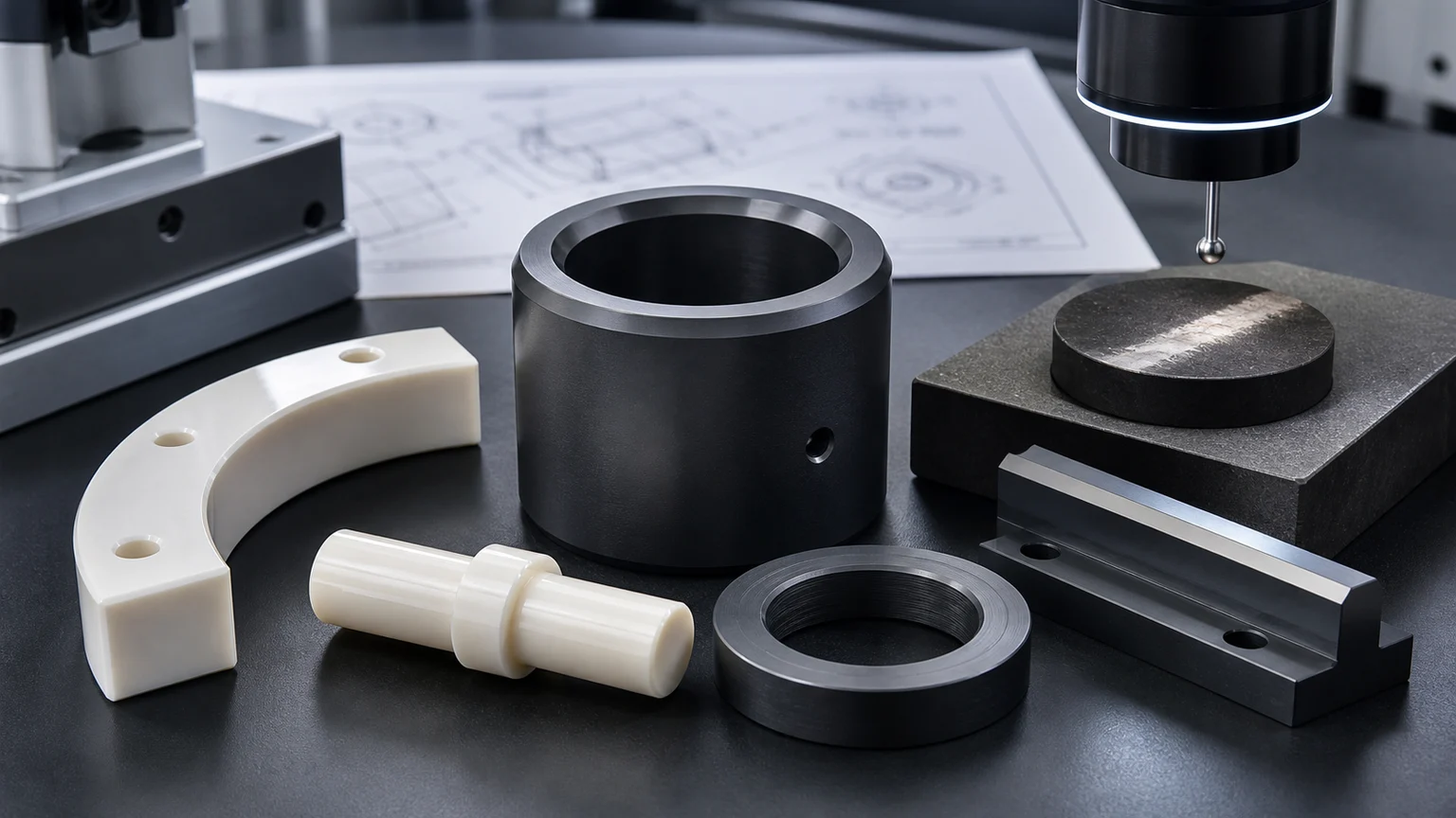
Industrial ceramic machining is valuable when a wear component must keep its shape, clearance, surface condition, or sealing face after metals, polymers, or coatings lose stability. The material helps, but the machined geometry, contact surface, edge condition, and inspection plan decide whether the ceramic part can work in the real assembly.
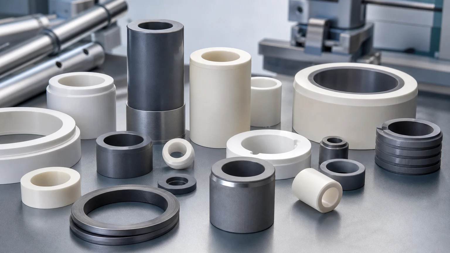
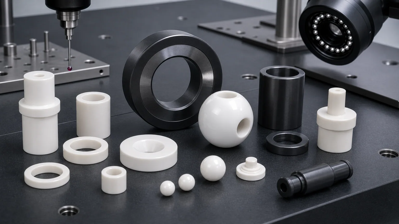
Wear-resistant ceramic components are used in pumps, valves, packaging equipment, textile machinery, abrasive material handling, chemical processing, semiconductor-adjacent equipment, industrial automation, metering systems, and high-speed guide mechanisms. Common RFQs include ceramic bushings, sleeves, shafts, rollers, pins, plungers, seal faces, valve seats, liners, wear plates, guide rails, nozzles, and custom sliding fixtures.
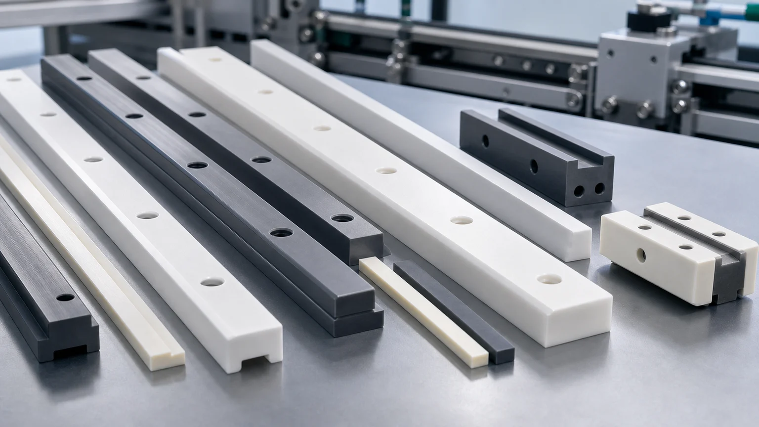
For long bars, strips, blocks, slots, and exposed sliding edges in conveyors or production machinery, use the focused ceramic guide rails for high-friction production lines guide. This page remains the broader material and component selector for wear applications.
The important sourcing question is not simply “Which ceramic is hardest?”
The better question is:
Which ceramic material, machined features, finish zones, and inspection evidence are needed for the actual wear mode?
That question should be answered before price, lead time, tolerance feasibility, or production route are confirmed.
Why Ceramics Are Used For Wear-Resistant Components
Technical ceramics can offer high hardness, low density, thermal stability, electrical insulation, corrosion resistance, and low wear under specific contact conditions. In the right design, a machined ceramic component can reduce scoring, galling, abrasive wear, chemical attack, or dimensional drift.
But wear resistance is not a single property. It depends on the complete system:
- Sliding speed and contact pressure.
- Abrasive particle size and hardness.
- Dry, lubricated, wet, vacuum, or chemical environment.
- Impact, vibration, or cyclic loading.
- Counterface material and roughness.
- Temperature and thermal shock.
- Alignment, clearance, and assembly method.
- Edge quality and surface integrity after machining.
A ceramic material can be excellent in one wear condition and unsuitable in another. That is why industrial ceramic machining RFQs should describe the wear mechanism, not only the part name.
Common Wear-Resistant Ceramic Materials
Material selection affects machinability, edge strength, surface finish, cost, and risk. Fired high-performance ceramics often require diamond grinding or abrasive finishing for tight features. Machinable ceramics can be useful for prototypes and special insulation roles, but they are not universal wear substitutes.
| Material | Typical wear-resistant use | RFQ review focus |
|---|---|---|
| Alumina Al2O3 | Wear liners, bushings, guide parts, insulating wear plates, valve parts | Purity, density, edge chipping, flatness, bore quality, and abrasive environment |
| Zirconia ZrO2 | Pins, plungers, sleeves, valve parts, precision wear mechanisms | Toughness advantage, temperature limit, fit, finish, and counterface condition |
| Silicon nitride Si3N4 | Rollers, guide sleeves, bearing-adjacent parts, high-speed wear features | Load, shock, roundness, bore/OD relationship, and surface finish |
| Silicon carbide SiC | Seal faces, wear rings, chemical wear parts, harsh-environment components | Lapped faces, edge quality, chemical media, and finishing cost |
| Aluminum nitride AlN | Wear-adjacent thermal and electrical parts | Thermal interface, insulation, flatness, and whether wear is the primary driver |
| Boron nitride BN | High-temperature contact or insulation parts in selected environments | Grade, temperature, atmosphere, and mechanical load |
| MACOR | Prototype fixtures or insulating parts with moderate mechanical demand | Suitability for final wear duty must be reviewed |
If the material is not fixed, send the operating environment and failure mode. A supplier can then review whether alumina, zirconia, silicon nitride, silicon carbide, or another grade is a better fit for machining and service.
Match The Ceramic To The Wear Mode
Different wear modes create different design priorities.
Abrasive wear usually comes from hard particles sliding or flowing across the part. Material hardness, surface finish, exposed edges, and replacement geometry matter.
Sliding wear depends on contact pressure, lubrication, counterface roughness, temperature, and alignment. Surface finish, roundness, and edge transitions often matter as much as hardness.
Erosive wear happens when particles or fluid strike a surface at speed. Nozzle bores, flow angles, wall thickness, and entrance/exit edges need review.
Fretting or vibration wear can damage small contact areas. Datum stability, contact geometry, and edge support become important.
Corrosive wear combines chemical attack with abrasion or sliding. Silicon carbide, alumina, or other ceramics may be considered, but media chemistry and temperature must be included in the RFQ.
The same material may need different machining controls depending on which wear mode dominates.
Wear Components Need Functional Geometry, Not Tight Tolerance Everywhere
Many wear-resistant ceramic RFQs become expensive because the drawing applies tight tolerance and low surface roughness to every face. That usually does not improve service life.
A better drawing separates:
- Finished sliding surfaces.
- Seal faces or valve seats.
- Bore and OD fit relationships.
- Datum faces used for inspection or assembly.
- Edges exposed to abrasive flow.
- Clearance pockets and non-contact surfaces.
- Mounting holes and fastening zones.
- Replaceable wear surfaces.
For a ceramic bushing, the ID, OD, roundness, concentricity, and edge condition may be critical, while the length or outer relief may have moderate requirements. For a wear plate, flatness and mounting hole edge quality may matter more than an overly tight outside profile. For a seal face, flatness, Ra, lapping method, and handling protection can dominate the RFQ.
Use tight requirements where function needs them. Relax non-contact geometry where possible.
Ceramic Bushings, Sleeves, And Shafts
Ceramic bushings and sleeves are often used where metal parts suffer adhesive wear, corrosion, insulation failure, or abrasive scoring. The main risks are not only material hardness. They are bore quality, wall thickness, edge chips, and fit.
Important drawing inputs include:
- ID, OD, length, and wall thickness.
- Concentricity or runout between ID and OD.
- Roundness and cylindricity where motion depends on it.
- Press fit, slip fit, or clearance fit condition.
- Chamfer or radius at both bore entries.
- Surface finish on the sliding bore or OD.
- Whether the component sees impact, vibration, or thermal cycling.
- Inspection method for the bore and fit relationship.
Thin-wall sleeves need additional review because grinding, measuring, and assembly can create fracture risk. If the sleeve is very thin, define which surfaces must be finished and which surfaces may be less critical. The related thin-wall ceramic sleeve RFQ guide covers this geometry in more detail.
Ceramic Liners, Wear Plates, And Guide Rails
Liners and wear plates are common in abrasive material handling, automation tracks, packaging systems, pump hardware, and chemical equipment. They look simple, but the quote depends on surface zones, hole edges, flatness, and mounting strategy.
Review these features:
- Wear face flatness and surface finish.
- Mounting hole diameter, edge break, and countersink condition.
- Slot or pocket radii.
- Bonding face or mechanical fastening method.
- Edge exposure to abrasive flow.
- Whether the liner is replaceable.
- Whether the ceramic part needs matched pairs or sets.
Avoid sharp exposed edges where abrasive flow or installation can chip the component. If countersunk holes or screw seats are required, define edge condition and load path. Ceramics do not tolerate point loading the same way ductile metals do.
Seal Faces, Valve Seats, And Pump Components
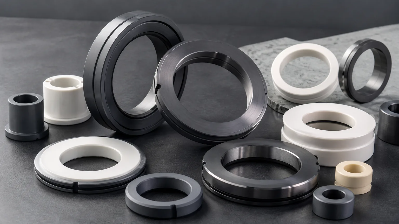
Silicon carbide, alumina, zirconia, and other ceramics may be used for seal faces, valve seats, pump plungers, metering pistons, and fluid-control components. These parts often require more than CNC shaping. They may need diamond grinding, lapping, controlled surface finish, and careful cleaning.
For seal and valve parts, specify:
- Sealing face location and width.
- Flatness or parallelism requirement.
- Surface roughness on the sealing band.
- Edge break around the sealing face.
- Fluid chemistry and temperature.
- Mating material and contact pressure.
- Leak, pressure, or functional test expectation if applicable.
- Packaging protection for lapped faces.
Do not apply a low Ra requirement to every surface unless every surface is functional. A local lapped band is often more practical than an entire part treated as a seal face. The ceramic lapped seal faces guide explains how flatness, Ra, edge condition, and leak risk should be reviewed together.
Nozzles, Orifices, And Flow Wear Parts
Ceramic nozzles and orifice inserts are used where flow carries abrasive particles, corrosive fluid, heat, or high velocity. In these components, the bore is not just a hole. It controls wear rate, flow behavior, and replacement life.
The RFQ should define:
- Bore diameter and tolerance.
- Bore length and taper allowance.
- Entrance and exit edge condition.
- Wall thickness around the bore.
- Flow direction and media.
- Particle size or abrasive content.
- Whether the bore needs polishing, grinding, or another finish.
- Inspection method for diameter, taper, and edge quality.
If the nozzle has a complex internal path, send both 3D CAD and a controlled drawing. Some internal features may require route review before feasibility is confirmed.
Surface Finish And Edge Quality Control Wear Life
Wear-resistant ceramic parts often fail early because the functional surface or edge was not specified clearly. Surface finish affects friction, sealing, particle retention, heat generation, and counterface wear. Edge quality affects chip initiation and crack risk.
Specify surface finish by face:
- Sliding bore.
- OD wear surface.
- Seal face.
- Guide rail top face.
- Abrasion-facing liner surface.
- Non-critical mounting face.
Also define whether edges are sharp, chamfered, radiused, or chip-controlled. A small chamfer can protect a part during assembly, but it may change flow, sealing, or fit if applied in the wrong zone.
For high-value surfaces, inspection may include profilometer measurement, optical review, CMM, roundness measurement, flatness evidence, or visual chip criteria. The surface finish and subsurface damage guide gives a deeper framework for specifying Ra and surface integrity without overpricing the whole part.
Design Rules For Wear-Resistant Ceramic Parts
Wear-resistant ceramic designs should reduce avoidable stress and point loading.
Useful rules include:
- Add radii to internal corners where tool access allows.
- Use chamfers or radii on handling and assembly edges.
- Avoid knife edges in abrasive flow paths.
- Keep thin walls supported.
- Avoid unnecessary deep narrow slots.
- Place datums on finished and measurable surfaces.
- Separate wear faces from mounting faces.
- Avoid point clamping on brittle ceramic surfaces.
- Define whether adhesive bonding, mechanical fastening, or shrink fit is used.
- Design replacement parts so the functional wear face can be inspected.
The ceramic CNC machining design rules page covers these manufacturability controls in more detail.
Inspection For Wear-Resistant Ceramic Components
Inspection should match the part function. A wear-resistant ceramic component may need dimensional inspection, surface finish inspection, or functional evidence depending on the application.
Common checks include:
| Feature | Typical inspection question |
|---|---|
| Bore and OD relationship | Is concentricity, roundness, or runout controlled? |
| Sliding face | Is the surface finish on the functional face defined? |
| Seal face | Is flatness and Ra measured on the correct band? |
| Mounting holes | Are hole edges protected from chips and point loads? |
| Wear liner face | Is flatness or thickness important to installation? |
| Nozzle bore | Is diameter, taper, and exit edge measurable? |
| Guide rail | Is the contact face straight, flat, and protected? |
| Edge condition | Are chip criteria visible and auditable? |
If acceptance evidence matters, include it in the RFQ before quotation. Inspection time can affect price and lead time as much as machining time.
RFQ Inputs That Prevent Quote Variance
For industrial ceramic machining of wear-resistant components, send:
- 3D CAD and controlled 2D drawing.
- Material grade, purity, or acceptable alternatives.
- Quantity, prototype or production intent, and revision status.
- Wear mode: abrasive, sliding, erosive, corrosive, fretting, or mixed.
- Counterface material and roughness if known.
- Load, speed, pressure, temperature, chemistry, and lubrication condition.
- Functional wear faces and non-critical faces.
- Bore, OD, flatness, parallelism, concentricity, or runout requirements.
- Surface finish by face or band.
- Edge break and chip criteria.
- Cleaning, packaging, and inspection documentation needs.
- Target timing for review, not a confirmed lead time.
If some requirements are unknown, state the application and failure problem. A useful review can often start from the operating condition and worn metal or polymer part history.
Supplier Review Questions
Before releasing a wear-resistant ceramic component for production, clarify:
- Which ceramic material best matches the wear mode and environment?
- Which faces need diamond grinding, lapping, or polishing?
- Which tolerances are functional, and which can be relaxed?
- Are there sharp edges, thin walls, or point loads that increase fracture risk?
- Can the required features be inspected with practical equipment?
- Does packaging protect finished wear faces and lapped surfaces?
- Is the part designed for replacement, alignment, and assembly without edge damage?
These questions reduce quote ambiguity and help prevent a hard ceramic material from being used in a weak mechanical design.
Practical Takeaway
Industrial ceramic machining can improve wear performance when material selection, contact geometry, surface finish, edge quality, and inspection are reviewed together.
For wear-resistant ceramic bushings, liners, shafts, rollers, seal faces, valve seats, nozzles, and guide components, do not rely on material hardness alone. Send the drawing, CAD, operating environment, wear mode, functional surfaces, surface finish, edge criteria, quantity, and inspection expectations. The machining route, feasibility, price, and lead time should be confirmed only after that review.
- Industrial ceramic machining
- Wear resistant ceramics
- Ceramic bushings
- Silicon carbide
- Zirconia