Published · CERAMIC CNC Engineering · Engineering Guide · 8 min read
Ceramic Thin-Wall Sleeve Machining RFQ Guide: Bore Concentricity, Wall Thickness, Roundness
How to prepare an RFQ for thin-wall ceramic sleeves, bushings, insulating tubes, precision bores, wall-thickness control, roundness, concentricity, and inspection.
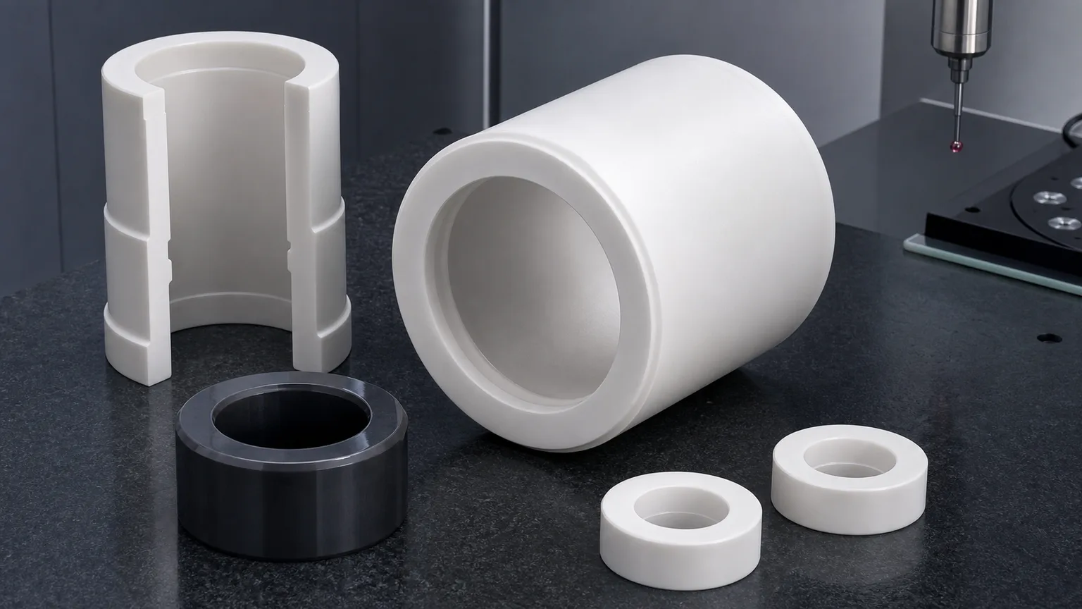
A thin-wall ceramic sleeve RFQ is not only an ID, OD, and length request. It is a wall-thickness, concentricity, roundness, datum, grinding pressure, edge integrity, and inspection problem. Send the drawing, CAD, material, wall section, functional bore, mating shaft or housing, tolerance map, surface finish, and measurement method before expecting a useful quote.
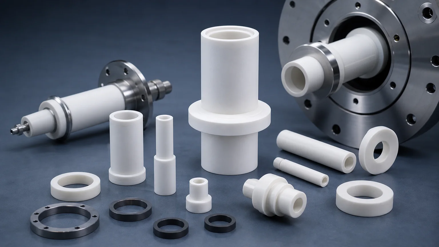
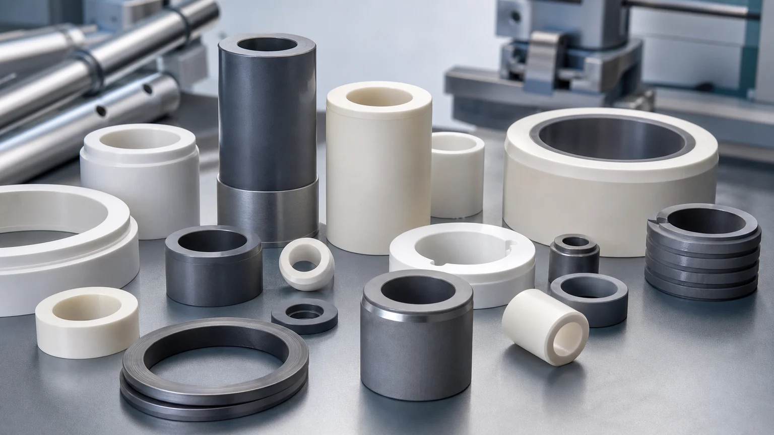
Thin-wall ceramic sleeves and bushings appear in electrical insulation, pump and valve hardware, bearing-adjacent guides, semiconductor fixtures, high-vacuum spacers, sensor housings, wear sleeves, and alignment components. The part may look simple in a CAD model, but ceramic sleeve machining is often controlled by the relationship between the bore, outside diameter, end faces, and wall thickness.
The useful first question is:
Which surface actually controls function: the inside bore, the outside diameter, the end faces, or the wall section between them?
If the answer is unclear, the supplier may quote a sleeve that meets nominal dimensions but fails assembly because the bore is not concentric to the OD, the wall is too thin to support finishing, the end face is not square enough, or the edge chips during handling.
Why Thin-Wall Sleeves Need A Dedicated RFQ
Metal sleeve drawings often assume turning, boring, and grinding logic that does not transfer directly to fired technical ceramics. Ceramics do not yield under tool pressure. They chip, crack, wear tools quickly, and often require diamond grinding, lapping, honing, or route-specific fixturing.
Thin-wall sleeves combine several risks:
- The bore may be long, small, or difficult to inspect through the full depth.
- The OD and ID may need concentricity even though each surface needs a different setup.
- Grinding pressure can create local damage or distortion risk on unsupported walls.
- End faces may control squareness, stack height, sealing, or electrical creepage.
- Chamfers and edge breaks can change usable length or mating fit.
- Material grade, fired density, and blank condition can change removal allowance.
- Inspection results can change depending on free-state, supported, or mandrel-mounted measurement.
That is why a thin-wall ceramic sleeve should not be priced from a STEP file alone when the bore or wall section is functional.
Typical RFQ Scenario
A common sourcing case is a ceramic insulating sleeve with a precision inner bore, a controlled outside diameter, and a thin wall used between a shaft, pin, electrode, probe, or housing. The buyer may ask for “tight concentricity” but not define the datum or measurement setup.
Before quote review, the supplier needs to know:
- Whether the bore pilots on a shaft or only provides clearance.
- Whether the OD locates in a housing or only provides insulation spacing.
- Whether the sleeve is compressed, clamped, bonded, or free-floating.
- Whether one end face is a datum, seal face, or spacer face.
- Whether chips at the bore edge, OD edge, or slot edge are unacceptable.
- Whether roundness, cylindricity, or total runout is the correct control.
Without that information, the same drawing can require very different machining and inspection routes.
RFQ Inputs That Matter
| RFQ input | Why it matters |
|---|---|
| Material and grade | Alumina, zirconia, silicon nitride, SiC, AlN, and MACOR change grinding route, chipping risk, and inspection approach |
| Fired or green state | Determines whether features are rough-formed before sintering or finished after firing |
| ID, OD, length, and wall thickness | Defines removal allowance, support method, and fracture risk |
| Functional surface | Separates critical bore, OD, end face, or datum from non-critical geometry |
| Fit condition | Shaft, pin, housing, adhesive, clamp, seal, or clearance fit changes tolerance logic |
| GD&T controls | Concentricity, runout, cylindricity, roundness, perpendicularity, and parallelism require clear datums |
| Surface finish | Bore Ra, lapped end faces, and OD finish affect wear, sealing, insulation, or assembly |
| Edge criteria | Bore lead-in, OD chamfer, end-face chip limits, and handling edges affect yield |
| Inspection evidence | CMM, roundness, air gauge, pin gauge, optical review, or custom fixture should match the failure mode |
If the sleeve is part of a stack, include mating parts or a section view. If it is an electrical insulator, include voltage class, clearance, creepage intent, and contamination constraints. If it is a wear sleeve, include speed, media, load, and mating material.
Decide The Functional Relationship First
Thin-wall sleeves are often over-specified because every dimension receives tight tolerance. A better drawing identifies the relationships that matter.
For a shaft guide, the bore size, bore roundness, bore finish, and end chamfer may matter more than cosmetic OD finish.
For a locating bushing, OD size, OD roundness, and OD-to-ID runout may matter more than overall outside appearance.
For an insulating spacer, length, end-face parallelism, edge condition, and creepage geometry may matter more than a very tight bore.
For a seal-adjacent sleeve, end-face flatness, perpendicularity, and surface finish may control the assembly even if the cylindrical surfaces are moderate.
Use tight controls only where they protect function. Otherwise, the RFQ becomes expensive without improving the part.
Bore, OD, And Wall-Thickness Controls
The most common tolerance conflict is asking for a tight bore, tight OD, thin wall, and tight concentricity without defining which surface is created first and how the part is supported during finishing.
Clarify:
- Minimum and maximum wall thickness.
- Bore tolerance and measurement depth.
- OD tolerance and whether it is full-length or zone-specific.
- Roundness or cylindricity requirement on ID and OD.
- Total runout or coaxiality requirement between ID and OD.
- Which face or diameter is the primary datum.
- Whether end faces must be square to the bore or OD.
- Whether measurement is free-state or supported on a mandrel.
For very thin sections, the supplier may need to review whether the part can survive internal grinding, external grinding, honing, lapping, or handling. Feasibility depends on material, size, wall length, blank route, and inspection method.
Process Route Review
A practical route may combine rough forming, green machining, sintering, and post-sinter finishing. For a high-precision fired ceramic sleeve, the final functional surfaces usually need diamond finishing after firing.
Route questions include:
- Can the blank be formed close enough to reduce grinding stock?
- Does the bore need rough forming before firing?
- Which surface becomes the datum for final grinding?
- Can the sleeve be supported without damaging the bore?
- Is internal grinding or honing needed for the bore?
- Are end faces lapped or ground after cylindrical features?
- Will chamfering occur before or after final bore finishing?
- Can the selected inspection method prove the specified GD&T?
The right answer is drawing-specific. A quote should not assume one universal sleeve route for all alumina, zirconia, Si3N4, or SiC parts.
Material Choice Changes The Risk
Alumina is common for insulation and cost-sensitive precision sleeves, but purity, density, and blank quality still matter.
Zirconia may help where toughness and reduced edge chipping are valuable, though fit, temperature, and environment must be reviewed.
Silicon nitride can be a strong candidate for wear and thermal shock conditions, especially when mechanical reliability matters.
Silicon carbide may fit harsh wear, chemical, or temperature exposure, but it is difficult to finish and should receive tight tolerances only where needed.
MACOR and machinable glass ceramics can support prototypes or lab fixtures, but they should not be treated as direct substitutes for production alumina, Si3N4, SiC, or zirconia without functional review.
Material selection should begin with failure mode, not only with a catalog property table. Use the ceramic material selection guide when the grade is not fixed.
Edge Quality And Bore Entry
Most sleeve failures begin at edges. A brittle ceramic bore with a sharp edge can chip during assembly, while an oversized chamfer can reduce bearing length, sealing width, or insulation distance.
Specify:
- Bore entry chamfer or radius.
- OD edge break.
- End-face edge chip limit.
- Whether chips are allowed on non-functional outside edges.
- Whether burr-like breakout, micro-chips, or grinding marks are acceptable.
- Whether visual inspection uses magnification and a defined zone.
“No chips” is not a measurable production rule unless the inspection magnification, zone, and acceptance size are defined. A better RFQ separates functional bore edges, handling edges, and non-critical edges.
Inspection And Acceptance
Match inspection to the functional risk:
| Requirement | Inspection to discuss |
|---|---|
| Bore size | Pin gauges, bore gauge, air gauge, optical, or CMM depending on size and tolerance |
| Bore roundness | Roundness machine, air gauge, or agreed section sampling |
| OD size and roundness | Micrometer, CMM, roundness measurement, or fixture-based check |
| ID-to-OD relationship | Total runout, coaxiality, or CMM datum measurement |
| Wall thickness | Section-based measurement, CMM, ultrasonic method, or controlled sampling when accessible |
| End-face squareness | CMM, runout check, or fixture method from the functional datum |
| Surface finish | Profilometer, bore finish method, or agreed visual/functional acceptance |
| Edge quality | Microscopy, visual standard, chip limit by zone |
Do not specify a tolerance that cannot be measured repeatably. If the sleeve is small, long, thin, or opaque, some internal features may need a different acceptance method than the one used for metal parts.
Common RFQ Mistakes
Avoid:
- Calling out tight concentricity without datum references.
- Using “TIR” without stating the setup and indicated surface.
- Applying the same Ra requirement to every surface.
- Making all edges sharp on a brittle ceramic sleeve.
- Asking for a very thin wall without defining handling and packaging.
- Treating the ID and OD as equally critical when only one controls fit.
- Quoting from CAD only when the 2D drawing contains the actual acceptance criteria.
- Requiring full inspection but not defining which dimensions need recorded evidence.
Practical RFQ Checklist
Send:
- STEP file and 2D drawing with revision.
- Material, grade, fired state, and blank/source requirement.
- ID, OD, length, minimum wall thickness, and functional zones.
- Mating shaft, housing, seal, electrode, or assembly context.
- Datum scheme and GD&T for roundness, runout, coaxiality, perpendicularity, or parallelism.
- Bore and OD surface finish requirements by face.
- Chamfer, radius, edge break, and chip criteria by zone.
- Inspection method, report requirements, and measurement condition.
- Quantity, target timing, packaging, and handling constraints.
Use the ceramic tolerance capability map for tolerance planning, the ceramic DFM design rules for wall and edge constraints, and the RFQ checklist before sending a production request.
Final price, tolerance feasibility, lead time, and inspection scope depend on the drawing, material, quantity, blank condition, and acceptance review.
- Thin wall ceramics
- Precision bores
- Tolerances gdt
- Ceramic sleeves
- Inspection