Published · CERAMIC CNC Engineering · Engineering Guide · 7 min read
AI Data Center Power Electronics Ceramic Parts: SiC Modules, Insulators, Thermal Interfaces
RFQ guide for precision ceramic parts used around AI data center power electronics, SiC power modules, high-voltage insulation, thermal interfaces, and test fixtures.
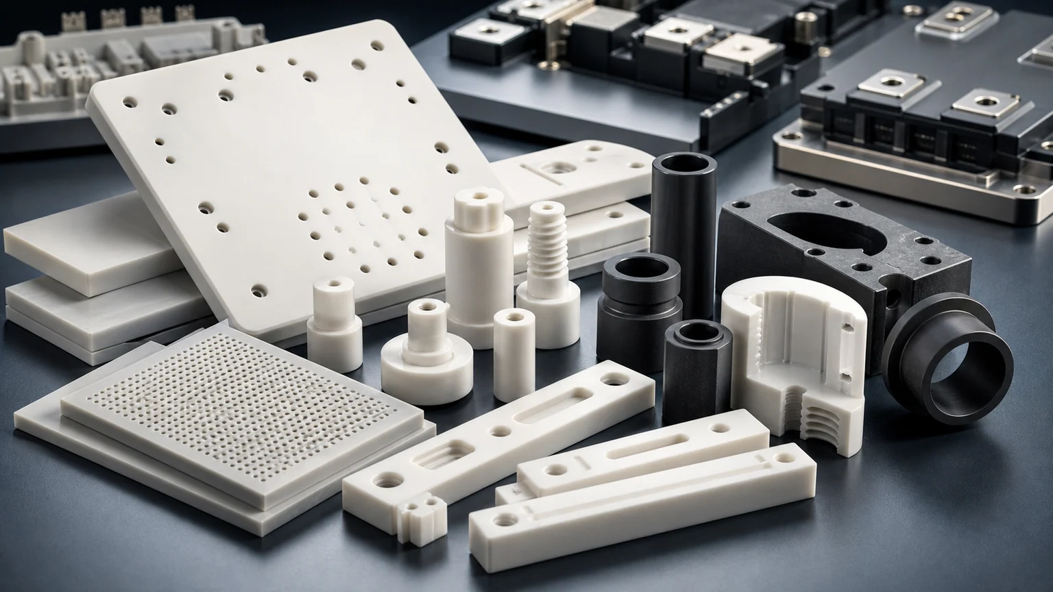
AI data centers are pushing power conversion harder. For ceramic machining buyers, the opportunity is not a generic heat-sink story. It is a set of high-voltage, high-heat, inspection-sensitive ceramic parts around SiC modules, insulation, fixtures, and thermal interfaces.
Precision ceramics enter power electronics because they combine electrical insulation, thermal behavior, dimensional stability, and wear resistance in places where polymers or metals are not enough. But ceramic performance depends on the drawing, blank state, edge quality, and acceptance method.
This guide explains how to prepare RFQs for precision ceramic CNC machining and diamond grinding in AI data center power electronics, SiC module development, high-voltage test hardware, and power-module support components.
Power Conversion Requirements That Shape the Ceramic RFQ
AI data centers are changing the power envelope. Infineon describes AI data center power supply designs moving toward 12 kW class systems, with silicon, SiC, and GaN used to increase efficiency and power density. That does not mean every ceramic part is inside the semiconductor package, but it does mean power conversion hardware is becoming denser, hotter, and more sensitive to insulation and thermal cycling.
Power module suppliers also point to technical ceramics directly. Rogers describes Si3N4 AMB substrates as a ceramic isolator brazed to copper for high-power electronics where reliability, heat dissipation, and partial discharge matter. Heraeus lists Si3N4 AMB substrates for high power density modules, and NGK describes AMB substrates as combining ceramic insulation with heat release for power modules.
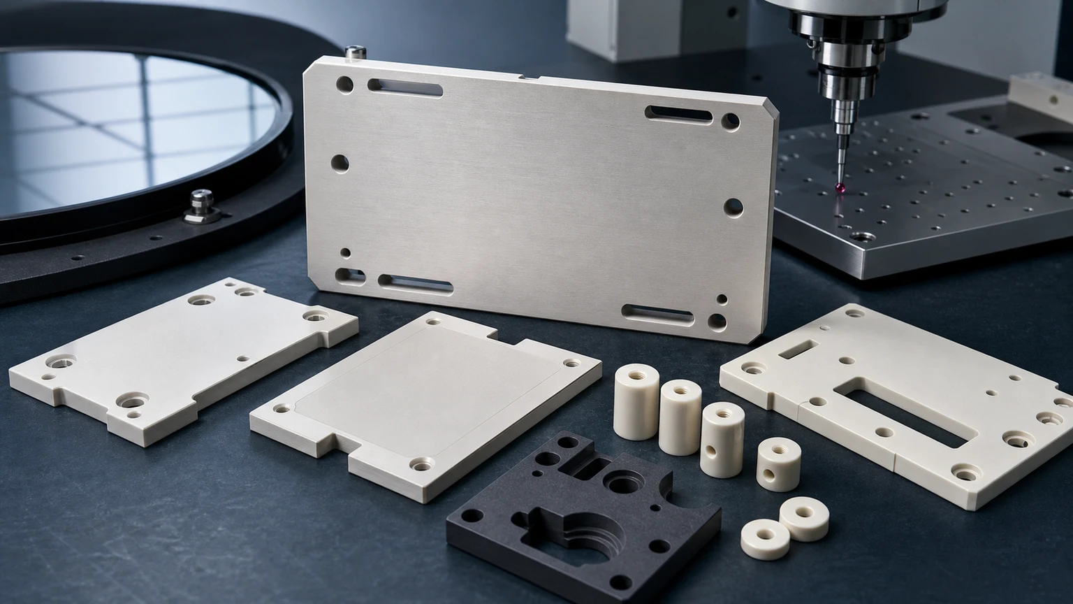
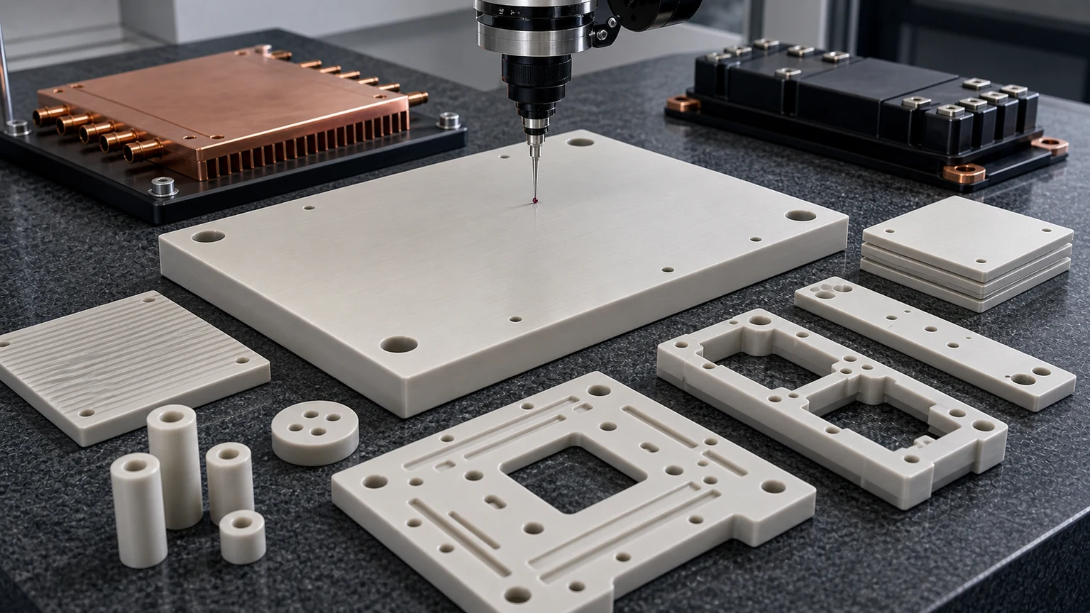
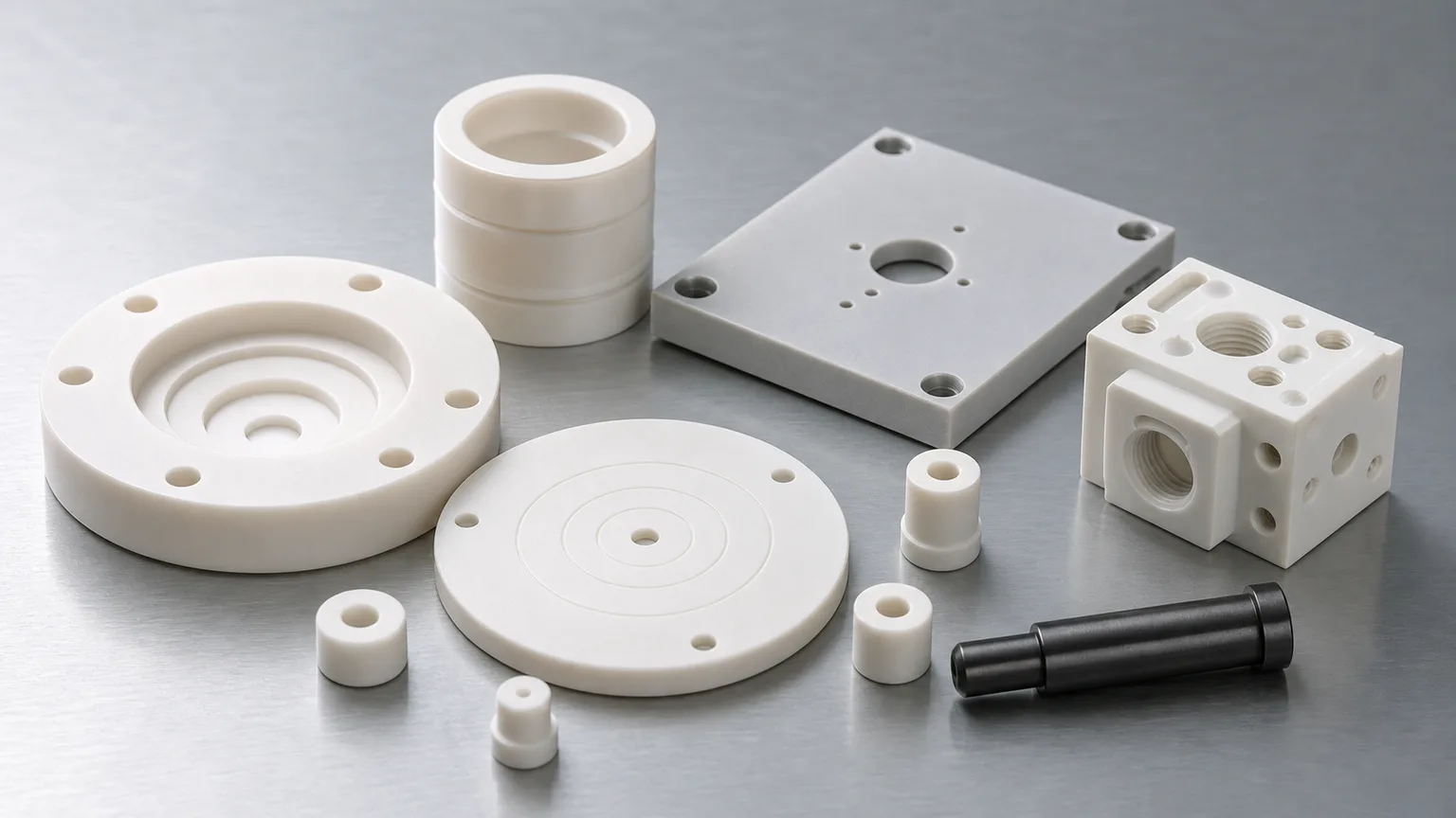
The machining requirement usually comes from an engineer or buyer who needs custom insulating plates, ceramic spacers, machined AlN or alumina parts, Si3N4 or SiC support hardware, test fixtures, or prototype ceramic components around the module.
Ceramic Parts That Appear Around AI Power Hardware
The ceramic machining RFQ usually belongs to one of these groups:
| Application area | Ceramic components to review | Main risk driver |
|---|---|---|
| High-voltage insulation | Alumina standoffs, sleeves, spacers, isolation plates | Creepage path, edge radius, surface cleanliness, and assembly stress |
| Thermal and electrical support | AlN plates, Si3N4 substrates, ceramic carriers, heat spreaders | Flatness, thickness, thermal cycling, chip-sensitive edges |
| SiC module test and assembly | Ceramic fixtures, alignment parts, pressure pads, guide parts | Parallelism, load distribution, wear, and repeatable positioning |
| Power conversion prototypes | MACOR or alumina insulating blocks, lab fixtures, small plates | Fast iteration versus final service material |
| Harsh test environments | SiC wear pieces, silicon nitride sleeves, ceramic bushings | Temperature, wear mode, chemical exposure, and finish requirement |
| Cooling-adjacent hardware | Insulating washers, ceramic manifolds, nozzles, spacers | Leak interface, hole quality, flatness, and thermal shock |
Do not assume that a ceramic material used in a substrate data sheet is automatically the right material for a machined fixture or insulator. Geometry, load, and inspection change the decision.
What Makes These Parts Difficult to Machine
AI data center power electronics parts often combine thin ceramic sections with demanding interfaces. The trouble usually appears in details:
- Thin AlN or Si3N4 plates that need flatness without edge chips.
- Countersunk holes near high-voltage creepage paths.
- Ceramic standoffs with tight concentricity and fragile shoulders.
- Alumina isolation plates with slots, pockets, and small corner radii.
- SiC or Si3N4 sleeves that need roundness and low Ra on running surfaces.
- MACOR prototype blocks that later must be redesigned for alumina or Si3N4 production.
- Fixture surfaces that look non-critical in CAD but actually control pressure distribution.
One common cost trap is applying the same tight tolerance to every surface. In a power module fixture, one lapped face and two datum bores may matter; the back side, outside profile, or non-contact pocket may not need the same precision.
Match Ceramic Material to Failure Mode
Start with the failure mode, then review machining feasibility.
| Failure mode or need | Material direction to consider | RFQ caution |
|---|---|---|
| Electrical insulation | Alumina, AlN, MACOR for prototypes, selected ceramics | State voltage class, creepage intent, surface finish, and edge radius |
| Thermal conductivity plus insulation | AlN, Si3N4-based materials, application-specific grades | Moisture handling, flatness, and thickness control must be reviewed |
| Mechanical support under cycling | Si3N4, zirconia, selected alumina grades | Load direction, clamp force, and temperature range affect the route |
| Wear or guide surfaces | Si3N4, SiC, zirconia, alumina | Roundness, Ra, edge condition, and lubrication or dry-running state |
| Prototype lab insulation | MACOR or machinable ceramics when service limits fit | Do not carry prototype geometry into production without material review |
| Harsh thermal or chemical exposure | SiC, alumina, fused silica, other reviewed ceramics | Tight finish on SiC can dominate cost and schedule |
The ceramic material selection guide explains this decision path in more detail.
RFQ Inputs for Power Electronics Ceramic Parts
Send more than a 3D model. For power electronics and high-voltage work, the supplier needs the context that controls risk.
- Drawing and CAD file with revision.
- Material grade or target material family.
- Whether equivalent grade review is allowed.
- Voltage class, creepage or clearance intent, and insulation surfaces.
- Operating temperature range and thermal cycling expectation.
- Load direction, clamp force, or pressure contact surfaces if relevant.
- Functional flatness, parallelism, thickness, bores, holes, or slots.
- Surface finish only on faces that affect thermal contact, wear, insulation, or sealing.
- Edge radius or chip criteria around high-voltage or mating areas.
- Quantity, first article needs, and repeat demand.
- Inspection evidence: CMM, flatness map, surface finish readings, optical review, or special report.
If the project is still at prototype stage, say so. A prototype ceramic fixture can be optimized for learning, while a repeat production part must be reviewed for yield, inspection time, and packaging.
Acceptance Evidence Should Match the Failure Consequence
Power electronics ceramic parts often fail outside the dimension that looked most important. A part can pass outside size but still create risk through a chipped edge, a bowed plate, a rough contact band, or an unmeasurable slot.
| Requirement | Evidence to discuss |
|---|---|
| Thermal contact face | Flatness map, thickness report, Ra reading, and protected packaging |
| High-voltage insulation | Edge condition, surface cleanliness, creepage geometry, visual review |
| Precision standoff or sleeve | CMM or optical dimensions, concentricity, roundness, and chamfer note |
| Test fixture reference face | Datum report, flatness, parallelism, and repeatability plan |
| Holes or slots | Diameter, position, edge breakout, countersink condition |
| Material confidence | Grade, certificate, customer-supplied blank record, or approved spec |
For surface-specific risks, use the surface finish and subsurface damage guide.
Design Rules That Reduce Quote Friction
Before sending a drawing, review these rules:
- Put tight flatness only on the faces that contact a module, heat spreader, seal, or fixture datum.
- Avoid sharp internal corners where a wheel radius or tool radius is unavoidable.
- Keep holes and countersinks away from fragile edges where possible.
- Mark ceramic edge break by functional zone instead of saying “deburred.”
- Give thin plates enough handling allowance and packaging requirements.
- Do not load ceramic threads in tension unless the load path has been reviewed.
- State whether a prototype can use MACOR or alumina while the final material remains under review.
- Define the first article inspection package before repeat quantity pricing.
The ceramic DFM guide is the right next read for slots, thin walls, threads, and chip-sensitive edges.
Practical Verdict
AI data center power electronics brings three engineering constraints together: SiC power density, high-voltage insulation, and thermal reliability. The machining RFQ still needs to stay grounded in the actual ceramic interface.
We should not claim a generic ceramic part will improve data center efficiency. The useful claim is narrower and more defensible: when drawings require insulation, flatness, thermal contact, wear resistance, or high-temperature stability, technical ceramics can be reviewed as part of the design and manufacturing route.
For a useful RFQ, send the drawing, material target, voltage and thermal environment, quantity, timing, functional faces, and inspection requirements through the RFQ page.
FAQ
Do you make complete SiC power modules?
No. This site is focused on precision ceramic machining and related ceramic component review, not complete semiconductor module assembly.
Can AlN be machined like alumina?
No. AlN has different handling, moisture, finish, and application concerns. The material grade and blank state must be reviewed before quoting.
Is Si3N4 always better than alumina for power electronics?
No. Si3N4 can be strong for thermal cycling and high-reliability modules, but alumina, AlN, zirconia, SiC, or machinable ceramics may fit different features and budgets.
What is the most common RFQ mistake?
Calling out tight tolerance and low Ra globally. Mark the thermal contact faces, insulation edges, datum bores, and fixture interfaces that actually control performance.
RFQ note: This guide supports early feasibility review. Final price, route, tolerance, lead time, and inspection plan should be confirmed only after drawings, materials, quantity, and acceptance requirements are reviewed.
- Power electronics ceramics
- AI data centers
- SIC power modules
- ALN ceramics
- Silicon nitride