Published · CERAMIC CNC Engineering · Engineering Guide · 5 min read
High-Voltage Ceramic Insulators RFQ Guide: Alumina, AlN, Si3N4
How to prepare RFQs for high-voltage ceramic insulators, spacers, sleeves, standoffs, power electronics fixtures, creepage paths, edge quality, and inspection.
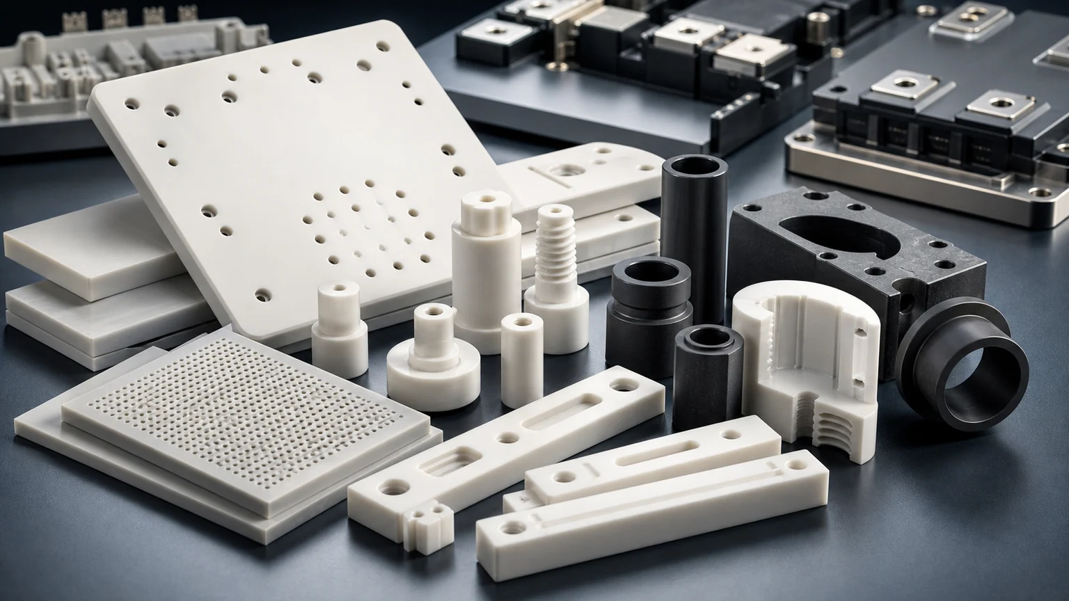
A high-voltage ceramic insulator RFQ is controlled by electrical function, geometry, edge quality, surface condition, assembly load, and environment. Send voltage, creepage and clearance needs, material target, drawing, mating hardware, and inspection expectations before treating the material name as enough.
High-voltage ceramic parts appear around power electronics, test fixtures, converters, vacuum hardware, plasma equipment, pulsed-power systems, sensors, and thermal assemblies. They may be alumina spacers, AlN plates, silicon nitride supports, zirconia sleeves, MACOR prototype fixtures, or SiC hardware where wear and temperature also matter. For semiconductor plasma etch or deposition tools specifically, also use the ceramic insulators for plasma etching and deposition equipment guide to connect insulation paths with chamber-adjacent cleaning, edge quality, thermal cycling, and inspection evidence.
The useful first question is:
What electrical failure mode is the ceramic part supposed to prevent?
The answer may be breakdown, tracking, arcing, leakage, partial discharge concern, thermal stress, mechanical cracking, or contamination on the surface.
Why The RFQ Must Include The Electrical Context
Ceramic machining suppliers can review geometry, material, tolerance, and finish. They cannot responsibly infer the electrical design from a drawing alone.
Include:
- Working voltage and peak voltage if known.
- AC, DC, pulse, frequency, or duty condition if relevant.
- Creepage and clearance requirements.
- Operating temperature and thermal cycling.
- Mating conductors, fasteners, coatings, or metallized areas.
- Contamination, humidity, vacuum, oil, coolant, or gas environment.
- Mechanical load, clamp force, or vibration.
- Whether the part is prototype, lab fixture, or production hardware.
This does not mean the machining supplier becomes the electrical designer. It means the quote can respect the surfaces and features that electrical performance depends on.
When the ceramic also surrounds a conductor or forms part of a vacuum boundary, use the ceramic feedthrough insulator guide to separate the machined ceramic body from metallization, brazing, hermetic sealing, leak testing, and final electrical qualification.
Ceramic Part Types
| Part type | RFQ focus |
|---|---|
| Alumina standoff or spacer | Hole quality, concentricity, edge break, surface cleanliness, load path |
| AlN insulating plate | Flatness, thickness, thermal path, chip-sensitive edges |
| Si3N4 support part | Strength, wear, thermal shock, finished bores, edge condition |
| Ceramic sleeve or tube | ID/OD concentricity, roundness, wall thickness, chamfer, crack risk |
| High-voltage fixture | Datum strategy, pocket geometry, conductor clearance, assembly repeatability |
| MACOR prototype insulator | Fast iteration, service limit review, production material transition |
Do not assume every prototype material can become the final material without redesign. MACOR can be useful for fast fixtures, but alumina, AlN, Si3N4, or other fired ceramics may require different feature rules.
Creepage And Clearance Are Geometry Requirements
Creepage and clearance are often treated as electrical design terms, but they become machining requirements when slots, ribs, grooves, holes, steps, and edge breaks define the path.
Clarify:
- Minimum wall thickness between conductors.
- Slot width and corner radius.
- Edge radius or chamfer near high-field regions.
- Whether sharp internal corners are allowed.
- Surface finish on the creepage path.
- Whether metallization, plating, or attached hardware changes the distance.
- Which surfaces must remain clean and free from chips.
If a creepage path depends on a very sharp rib or thin wall, the DFM review should happen before price.
Surface Finish And Edge Quality
For high-voltage ceramic parts, surface quality is not only cosmetic. Chips, cracks, grinding damage, contamination, and sharp edges can affect assembly and electrical reliability.
Specify:
- Critical insulating surfaces.
- Allowed chips or edge breakout.
- Chamfer or radius requirements.
- Surface finish only where it matters.
- Cleaning and packaging requirement.
- Whether sharp conductor-adjacent edges need controlled rounding.
Avoid a blanket “polish all” requirement unless it is justified. It may increase cost while failing to define the edge or cleanliness issue that matters.
Material Selection Should Follow Function
Material choice depends on electrical, thermal, mechanical, and machining needs.
| Material direction | Common RFQ reason | Review caution |
|---|---|---|
| Alumina | General insulation, spacers, standoffs, fixture plates | Grade, fired state, and edge quality affect machining route |
| AlN | Insulation with thermal conductivity | Edge chips, surface condition, and flatness can drive cost |
| Silicon nitride | Strength, thermal shock, wear, support hardware | Geometry and finished bores need early review |
| Zirconia | Tough precision sleeves or wear-adjacent parts | Electrical and thermal context should be checked |
| MACOR | Prototype fixtures and lab trials | Service limits and production transition must be reviewed |
| SiC | Wear, plasma, heat, or harsh environment | Conductive grades and application context must be understood |
Use the material selection guide if the material is still open.
Inspection Evidence
Inspection should prove the feature that controls acceptance:
| Requirement | Evidence to discuss |
|---|---|
| Hole and bore fit | CMM, pin gauge, ID/OD report, roundness where needed |
| Creepage features | Dimensional inspection of slots, ribs, spacing, and edge condition |
| Flatness or thickness | Flatness report, thickness map, parallelism to datum |
| Edge quality | Visual standard, microscope image, maximum chip size |
| Surface finish | Ra report on named insulating or contact faces |
| Cleanliness | Cleaning method, packaging, no residue requirement |
| Prototype function | Customer electrical test, sample report, or route review |
If the final electrical test is performed by the customer, state that. The machining RFQ can then focus on the geometry and surface evidence needed before that test.
Common RFQ Mistakes
Avoid:
- Sending only “alumina insulator” with no voltage or assembly context.
- Placing holes too close to high-voltage edges without chip limits.
- Using sharp internal corners where ceramic machining needs relief.
- Applying tight tolerance to non-functional outside surfaces.
- Asking for lapped finish on all faces instead of insulating paths or contact pads.
- Treating MACOR prototype success as proof that fired alumina or AlN production will be identical.
- Omitting cleaning and packaging for high-voltage surfaces.
- Not saying whether metallization, coatings, or attached copper parts will change spacing.
Practical RFQ Checklist
Send:
- STEP file and drawing.
- Application and voltage condition.
- Material target and allowed equivalent review.
- Creepage, clearance, and conductor locations.
- Critical insulating surfaces and edge requirements.
- Hole, bore, slot, and wall-thickness details.
- Surface finish, flatness, and cleanliness needs.
- Mating hardware, clamp load, or fixture context.
- Quantity, timing, and prototype or production intent.
- Inspection reports or customer test requirements.
Use the AI data center power electronics ceramic guide for power-module context and the DFM guide for feature review before sending the drawing.
- High voltage insulation
- Alumina
- ALN ceramics
- Silicon nitride
- Power electronics ceramics