Published · CERAMIC CNC Engineering · Engineering Guide · 8 min read
Precision Ceramic Machining for High-Performance Industrial Components
How engineers should review precision ceramic machining for industrial components, material selection, diamond grinding, tolerances, surface finish, inspection, and RFQ readiness.
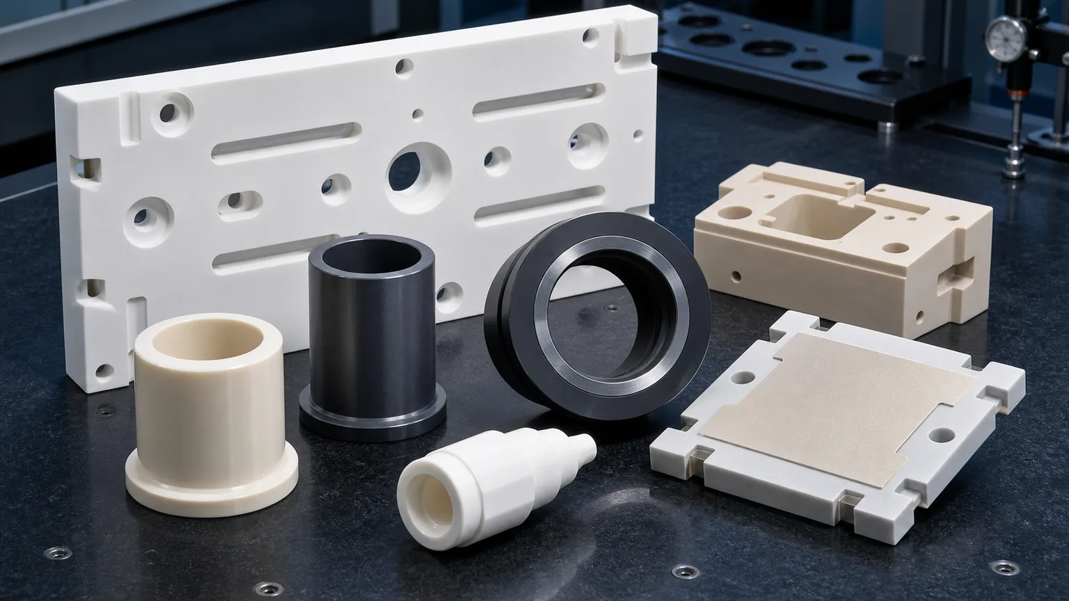
Precision ceramic machining is useful when a component must keep its geometry, insulation, wear resistance, thermal behavior, or chemical stability in conditions where metals or plastics create risk. The quote cannot be reduced to material name and quantity. It depends on drawing review, ceramic grade, blank state, functional surfaces, tolerance map, edge criteria, surface finish, and inspection method.
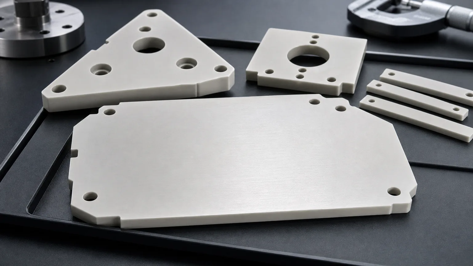
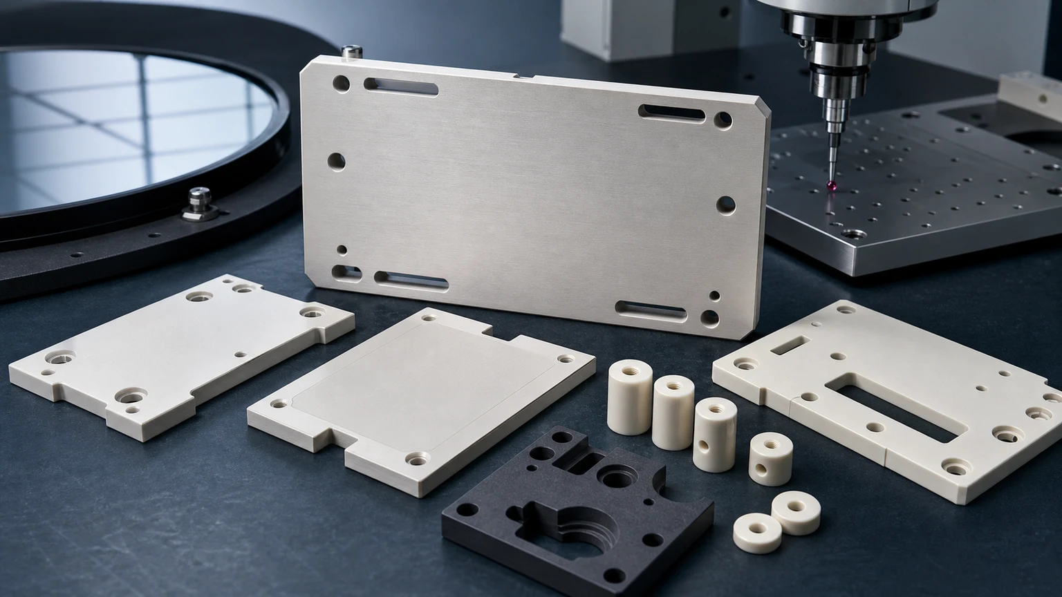
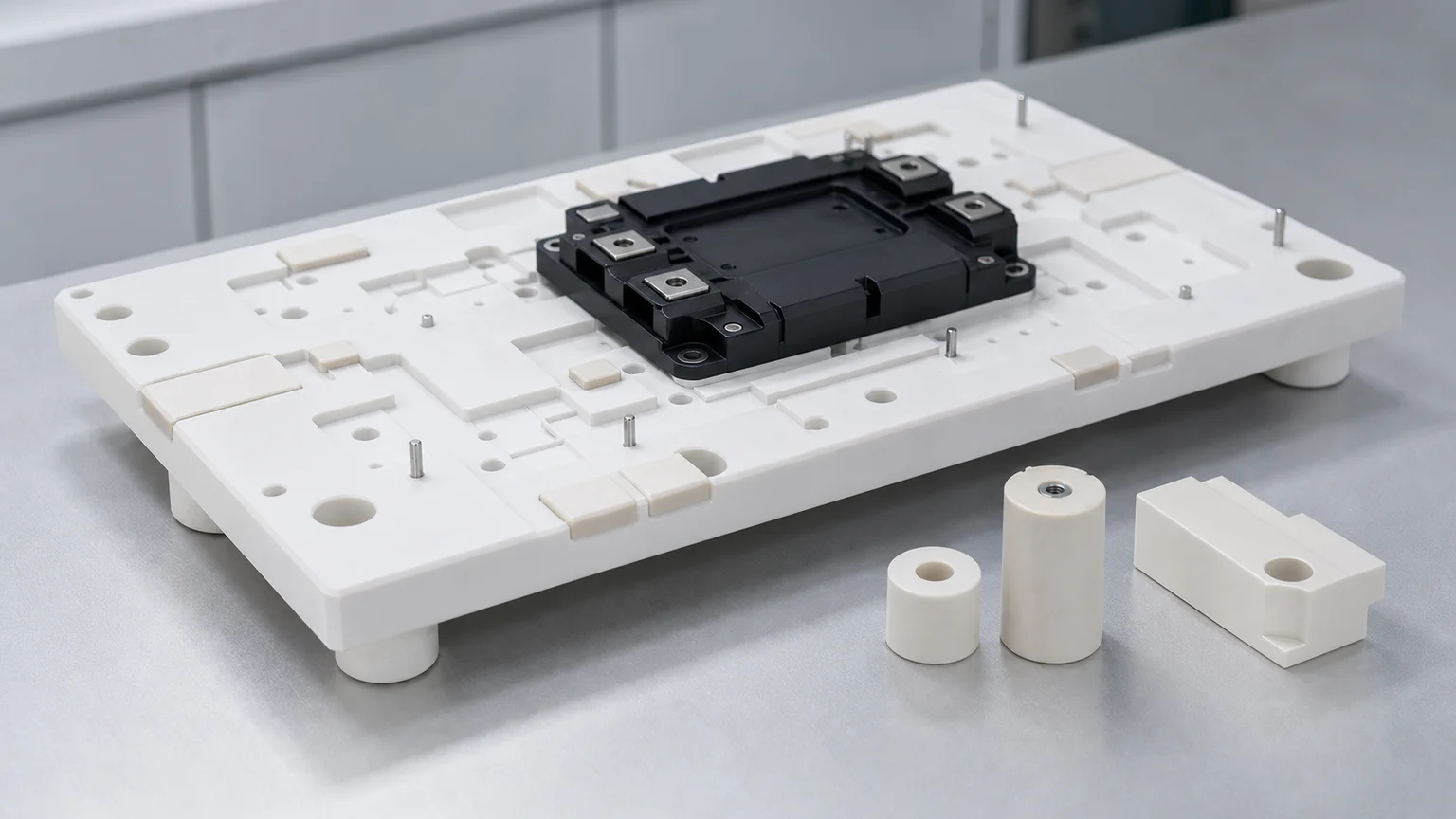
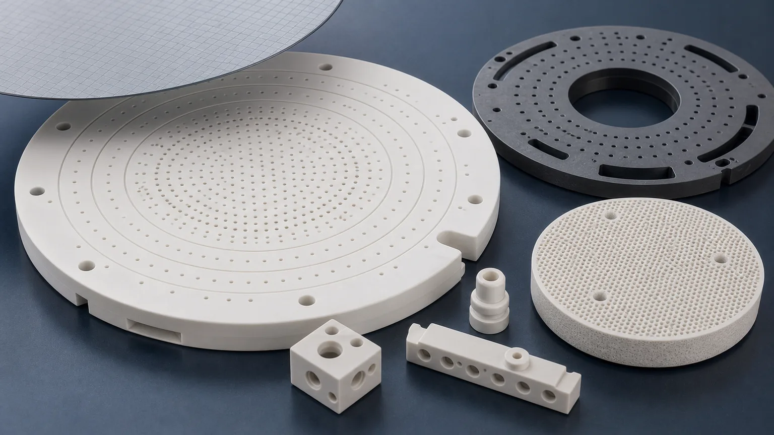
High-performance industrial ceramic components appear in semiconductor tools, electrical insulation, power electronics, vacuum systems, chemical processing, wear assemblies, metrology fixtures, thermal equipment, and precision automation. The parts may be simple plates, sleeves, rings, nozzles, spacers, guide rails, seal faces, or custom fixtures, but their value usually comes from the combination of material performance and controlled machining.
The practical question is not “Can this ceramic be machined?”
The better question is:
Which features must be finished, measured, protected, and documented so the ceramic part can work in the real assembly?
That question should drive the RFQ before price, lead time, or tolerance feasibility is confirmed.
What Precision Ceramic Machining Actually Includes
Precision ceramic machining can include several routes:
- Green machining before sintering when the blank route and shrinkage behavior are suitable.
- Post-sinter CNC machining for accessible fired ceramic features.
- Diamond grinding for tight faces, bores, OD/ID relationships, flatness, slots, and datum surfaces.
- Lapping for seal faces, precision flats, parallels, and low-Ra functional interfaces.
- Polishing when the surface condition is functional, not merely cosmetic.
- Micro-drilling, ultrasonic machining, or laser assistance for small holes and delicate flow features.
- Edge break, chamfering, cleaning, and protected packaging for chip-sensitive surfaces.
Most high-performance ceramics cannot be treated like ordinary metal parts. Fired alumina, zirconia, silicon nitride, silicon carbide, and aluminum nitride usually need abrasive finishing or diamond grinding for tight requirements. Machinable ceramics such as MACOR and some boron nitride grades can support faster prototype machining, but they are not universal substitutes for sintered structural ceramics.
Materials Used For Industrial Ceramic Components
The ceramic grade is not a minor purchasing detail. Material choice affects machinability, strength, chipping risk, finishability, cost, delivery timing, and inspection.
| Material | Common precision-machined use | RFQ note |
|---|---|---|
| Alumina Al2O3 | Insulators, spacers, wear plates, sensor parts, high-vacuum hardware | Specify purity, density, fired state, functional faces, and edge criteria |
| Zirconia ZrO2 | Pins, plungers, bushings, wear components, guide features | Review toughness advantage, temperature limit, fit condition, and surface finish |
| Silicon nitride Si3N4 | Wear parts, rollers, guide sleeves, bearing-adjacent parts, thermal shock applications | Define load, contact mode, roundness, bore quality, and inspection evidence |
| Silicon carbide SiC | Seal faces, wear rings, semiconductor-adjacent parts, chemical and high-temperature hardware | Apply tight tolerances only where function needs them; finishing cost can rise quickly |
| Aluminum nitride AlN | Thermal management parts, electrical insulation, power electronics fixtures | Protect thermal-interface faces and define flatness, Ra, and cleaning requirements |
| MACOR and machinable glass ceramic | Prototypes, lab fixtures, electrical test hardware, low-volume precision parts | Useful for speed and machinability, but validate whether it fits the production environment |
| Boron nitride BN | High-temperature insulation, nozzles, molten-metal-adjacent and thermal process parts | Define grade, atmosphere, temperature, and mechanical load before machining assumptions |
If the exact grade is not fixed, send the failure mode and environment: temperature, wear, load, voltage, vacuum, media chemistry, thermal cycling, cleanliness, and inspection needs. The material decision should be reviewed against the part’s job, not only a catalog property.
High-Performance Does Not Mean Tight Tolerance Everywhere
Many ceramic drawings become expensive because every face receives a tight tolerance or low Ra note. That usually does not improve function.
A better drawing separates:
- Functional seal faces.
- Finished datums.
- Bearing or sliding surfaces.
- Insulating creepage paths.
- Heat-transfer faces.
- Flow-control holes or nozzles.
- Alignment bores.
- Handling edges.
- Non-critical outside profile.
For example, a ceramic spacer may need excellent length control and parallel end faces, but moderate OD tolerance. A seal ring may need lapped flatness and Ra on one band, while the outside profile can remain less critical. A semiconductor fixture may need edge and cleanliness control more than a very tight non-functional pocket.
The RFQ should tell the supplier where precision creates value.
Design Rules That Reduce Machining Risk
Ceramics are strong in compression but vulnerable to tensile stress, sharp transitions, local flaws, and edge damage. Design decisions should reduce avoidable fracture risk.
Important design controls include:
- Avoid sharp internal corners when a radius can be used.
- Keep holes, slots, and grooves away from fragile edges unless the feature is essential.
- Define minimum wall thickness for sleeves, pockets, and frames.
- Avoid long unsupported thin sections without discussing fixture and handling risk.
- Add practical chamfers or radii to bore entries, seal lead-ins, and handling edges.
- Mark which surfaces can remain as-sintered or standard-ground.
- Define datums on stable, finished, inspectable features.
- Avoid global notes such as “all surfaces Ra 0.2” unless every surface truly needs it.
Use the ceramic DFM design rules when the part has holes, slots, thin walls, pockets, internal radii, or chip-sensitive edges.
Process Route: Green Machining, Fired Machining, Grinding, Lapping
The process route should be selected after reviewing material, feature geometry, quantity, and acceptance criteria.
Green machining may reduce shaping cost when the ceramic can be machined before sintering and shrinkage can be controlled. It is useful for near-net features, pockets, holes, and profiles when the final tolerance allows it.
Post-sinter machining is used when final accuracy, functional datums, flatness, sealing, or bore quality must be controlled after firing. It usually costs more because the ceramic is already hard and brittle.
Diamond grinding is often required for precise faces, OD/ID relationships, flatness, parallelism, slots, datum pads, and controlled bores. Grinding route planning should include setup sequence, wheel access, stock allowance, and inspection method.
Lapping is used for precision flats and seal faces when flatness, parallelism, or low-Ra surfaces are functional. It should be applied to selected faces, not assumed for an entire part.
For a deeper route comparison, see green machining vs hard machining.
Tolerances, GD&T, And Measurement Method
Tolerance feasibility is not universal. It depends on material, size, geometry, datum strategy, process route, and measurement method.
Before specifying tight values, clarify:
- Which feature controls assembly or performance.
- Whether the requirement applies to as-sintered or post-sinter finished surfaces.
- Which datum establishes the relationship.
- Whether the part is measured free-state or fixtured.
- Whether CMM, optical measurement, profilometry, flatness mapping, roundness, or a custom gauge proves acceptance.
- Whether the tolerance should be size, profile, flatness, parallelism, perpendicularity, runout, coaxiality, or position.
A drawing that calls out tight tolerances without stable datums often creates quote variance. The supplier may be forced to assume fixturing and inspection logic. Use the ceramic tolerance capability map to align feature type, route, and acceptance.
Surface Finish And Edge Quality
Surface finish should be reviewed by function. A low Ra value may matter on seal lands, sliding surfaces, thermal interfaces, optical-adjacent contact areas, and vacuum sealing faces. It may not matter on an outside surface that only provides clearance.
For each functional face, define:
- Required Ra or finish class.
- Whether grinding, lapping, or polishing is expected.
- Whether subsurface damage or micro-crack risk must be controlled.
- Whether visual inspection, microscopy, or functional testing is needed.
- Whether cleaning, packaging, and handling restrictions apply.
Edges need the same discipline. In ceramics, edge break is not cosmetic. It can prevent chips, reduce stress concentration, protect mating parts, and improve assembly yield.
Avoid ambiguous notes such as “no chips” or “sharp edge.” Instead define critical zones, allowable chip size, inspection magnification, and whether edge rounding is acceptable. The surface finish and subsurface damage guide explains why finish requirements should be assigned by face.
Industrial Applications Where Precision Ceramics Fit
Precision ceramic machining is strongest when the part needs one or more of these functions:
| Function | Example components | Review focus |
|---|---|---|
| Wear resistance | Bushings, guide rails, rollers, shafts, plungers | Contact surface, edge stability, roundness, mating material |
| Electrical insulation | Spacers, sleeves, standoffs, feedthrough parts | Creepage path, edge radius, surface condition, assembly stress |
| Thermal management | AlN plates, heat spreaders, power module fixtures | Flatness, Ra, cleanliness, thermal-interface faces |
| Chemical resistance | SiC parts, alumina flow components, valve seats | Media, temperature, seal face, cleaning method |
| Vacuum and clean systems | Ceramic chucks, spacers, rings, fixture parts | Flatness, particle-sensitive edges, cleaning, leak-critical faces |
| Precision alignment | Bores, datum pads, metrology fixtures, locating parts | Datum scheme, coaxiality, CMM evidence, packaging |
| Flow control | Nozzles, orifices, manifolds, micro-hole plates | Diameter, taper, breakout, flow test, blockage risk |
The same material can serve different applications, but the drawing and acceptance gate must change with the function.
RFQ Inputs That Prevent Quote Variance
Send the following before expecting a reliable quotation:
- 2D drawing with revision and a STEP or native CAD file.
- Material grade, purity, density, fired state, and blank/source requirement.
- Quantity, prototype target, repeat-order expectation, and target timing.
- Functional surfaces and non-critical surfaces.
- Datum scheme and critical GD&T.
- Surface finish by face, not one global note.
- Edge break, chamfer, radius, and chip criteria by zone.
- Service environment: temperature, voltage, wear, media, vacuum, thermal cycling, or cleanliness.
- Inspection method and report requirements.
- Packaging and handling requirements for fragile edges and precision faces.
If you are not sure which ceramic material fits the application, start with the ceramic material selection guide. If the part is ready for quotation, use the custom ceramic CNC machining RFQ checklist.
Supplier Review Questions
A good ceramic machining review should answer:
- Which requirements are functional and which are only inherited from the CAD model?
- Which features are finished after sintering?
- Which features can remain as-sintered or standard-ground?
- Where does diamond grinding or lapping control the outcome?
- Which edges create chipping risk?
- Which surfaces must be protected during cleaning and packaging?
- Which measurement method proves acceptance?
- Which assumptions affect price and lead time?
For procurement teams comparing suppliers, the ceramic CNC machining buyer guide gives a narrower view of capability evidence, cost drivers, lead time, inspection packets, and acceptance gates.
If those questions are not answered, the RFQ may still produce a number, but the number will include hidden assumptions.
Practical Takeaway
Precision ceramic machining works best when engineering, procurement, and the supplier review the part as a performance system: material, geometry, process route, surface integrity, inspection, and packaging. A high-performance ceramic component is not high-performance because every dimension is tight. It is high-performance because the right features are controlled, the right ceramic grade is selected, and the acceptance evidence matches the failure mode.
Final feasibility, tolerance, price, lead time, and inspection scope should be confirmed only after reviewing the drawing, material, blank condition, quantity, functional requirements, and acceptance method.
- Precision ceramic machining
- Industrial ceramics
- Diamond grinding
- Material selection
- RFQ checklist